Shortcuts & Models
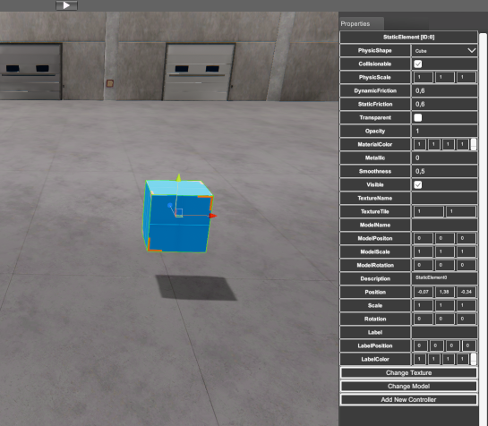
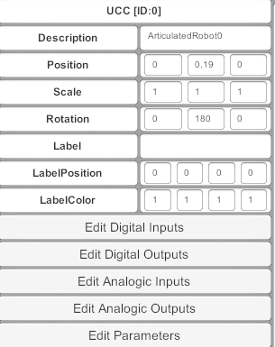
Once a component is selected can be customized by selecting the Property Grid (right side) and typing the desired value for each one of their properties:
But for the most used operations, some keyboard shortcuts can be used in order to speed up the machine set up. For the transform data for each component special commands are available. The transform data of the components stores the data regarding Position, Rotation and scale in the space for each of three axes.
Once a component is selected, press ‘W’ key (to move), ‘E’ key (to rotate) or ‘R’ key (to scale) the component. Then a different gizmo will be placed over the component to show the operation type to be applied over the component.
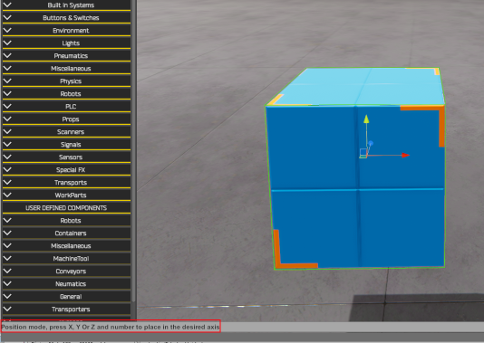
When W key is pressed is show Position mode.
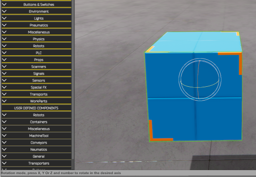
When E key is pressed is show Rotation mode.
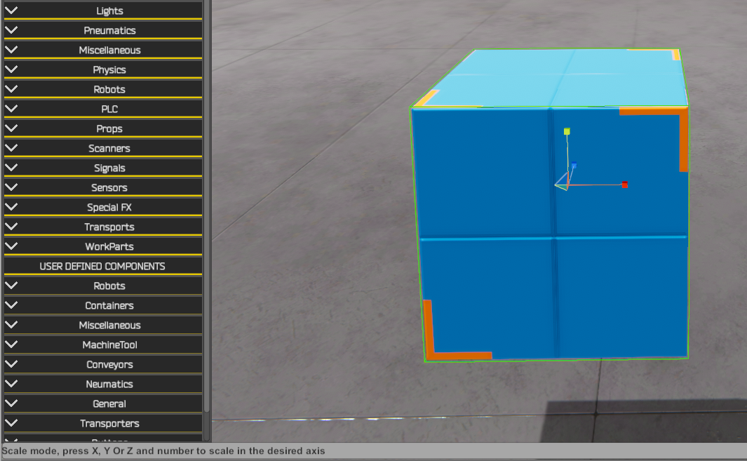
When R key is pressed is show Scale mode.
See also how is indicated by the lower status bar text:
- With W key:

- With E key:

- With R key:

- With T key: Box scale mode is active. Then is possible to scale the component stretching or narrowing each of the 6 sides: up, down, left, right, front, back. Leaving the rest anchored.
Then, once the W or E or R keys are pressed, the user must to press the ‘X’ key to move, rotate or scale in X axis, or the ‘Y’ key to move, rotate or scale in Y axis, or the ‘Z’ key to move, rotate or scale in Z axis. Or press ‘A’ key to select all axes then you can move, rotate or scale all axes at same time.
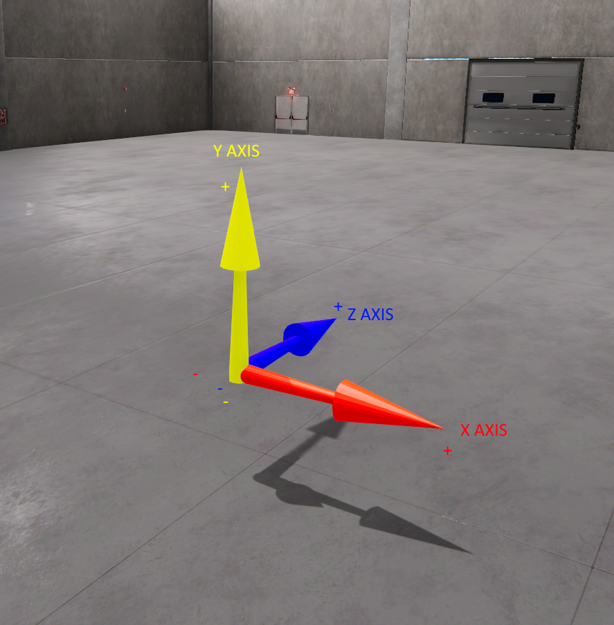
Axis nomenclature and direction
Now is necessary to type the number where we want to place, rotate or scale the axis component, only are valid numeric keys (0,1,2,3,4,5,6,7,8,9), point ‘.’ or comma ‘,’, and plus ‘+’ and minus ‘–‘ keys. Use backspace to delete the last input key. Once the number is entered, press Enter key to confirm. Press Scape key anytime in the sequence to cancel the operation.
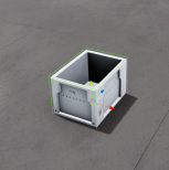
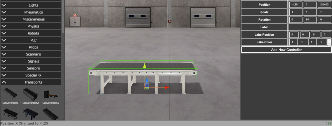
For example, the keys sequence to move the conveyor in the following machine will be:
- Click over the conveyor component and press W key to enter in Position mode:
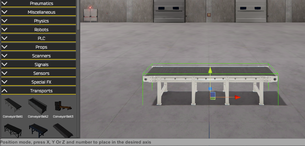
- Press ‘X’ Key to select the axis X to be positioned in:
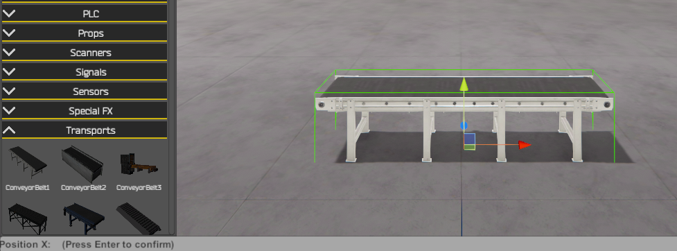
- Press the keys ‘1’ + ‘.’ + ‘2’ + ‘5’ + ‘-‘ to type the value -1.25
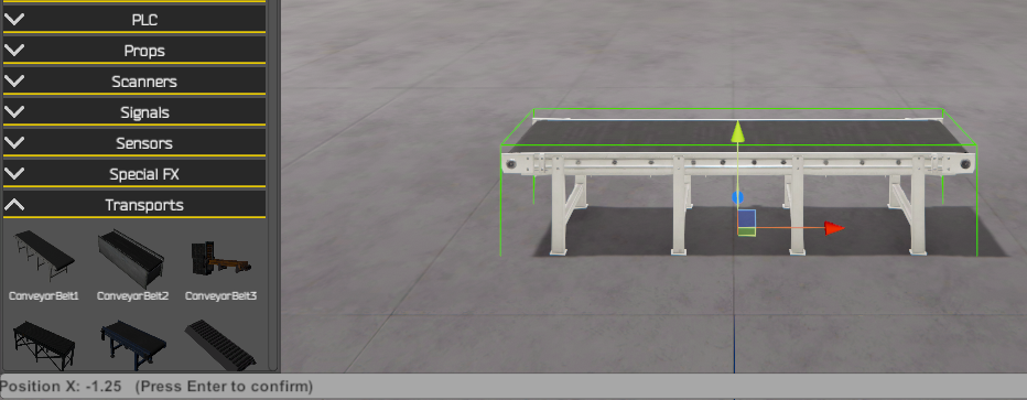
- Finally press Enter key to confirm and place the component in the new position
For Static, Dinamyc and WorkPart components, there is a special functionality. Because these components can accommodate a 3D model within their collision shape (physical shape), it is possible to graphically scale the collision shape without affecting the scale or position of the model it contains. Using the Scale or Box Scale gizmo, holding down the Left Shift key allows you to adjust the scale of the collision shape without affecting the model. It can also be used to adjust the model's position within the collision shape.
Change the communication speed with I/O Drivers
For applications where the speed of simulation and signal exchange with the PLC/Simulator or third-party SW, is critical due to the need for more exhaustive synchronization, it is possible to change the communication speed with the drivers.
If you need to change the poll rate of the communication driver, you can do so by modifying the following file located at:
C:\Nirtec\Machines Simulator 4\Drivers\DriversList.ini
You must change the Key:
[PollRate]
Value = 100
By default the poll rate is 100 milliseconds. You can change it to the desired value (value expressed in milliseconds).
Note: Certain communication protocols may not accept certain Poll rate values, so it will be limited to the maximum speed allowed by the given driver.
It is also possible to modify the time interval frequency for physics engine calculations and operations. This time also affects communication with the I/O drivers, as data will be updated between Machines Simulator and the driver manager based on this scheduled time. By default, the interval is 20 milliseconds, but it can be reduced to as little as 10 ms. This means that the fastest information exchange time between Machines Simulator and the communication drivers will be 10 ms if configured this way.
In order to change this value, you must change the value located in the following file:
C:\Nirtec\Machines Simulator 4\ms4bin_Data\config.ini
[Settings]
Phys=20
This value is set to 20 ms by default, you can change it to a minimum time of 10 ms or a maximum of 40 ms.
Therefore, if we want to maximize the communication speed between Machines Simulator and any communication driver, it will be necessary to modify these two files with the following values:
C:\Nirtec\Machines Simulator 4\Drivers\DriversList.ini
[PollRate]
Value = 10
C:\Nirtec\Machines Simulator 4\ms4bin_Data\config.ini
[Settings]
Phys=10
In this case the digital/analog inputs/outputs are updated every 10 milliseconds.
Media Library
Machines Editor has available a media library composed by textures, 3D models and sounds. Some components like Static and Dynamic Elements, Plane and WorkParts have a texture and/or a model property, if you click the respective button, the texture or model windows appears and you can choose the texture or model to apply to this component. The Sound library is used to ear the available sounds, you can use it in the components or installation programming to give your components or installations sounds capabilities.
Can I add new media content?
Yes, you can add to your project your own Textures (jpg or png file format), your own audio files (wav files) or 3D models (obj format). To do it, copy it in the desired folder and use the script functions to call the Textures and audio files for the components where you want to customize.
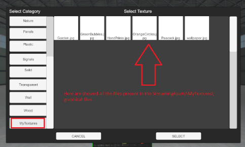
From version 3.2.2 you can select from Texture window Selector your own graphical files, to do it, copy your files in the Machines Simulator 4 installation folder\ms4bin_Data\StreamingAssets\MyTextures\
To add new 3D models or Components, go to Appendix: How to add new 3D Models to Machines Simulator 4 & Machines Simulator VR
Physic Shape vs Model Properties vs Components
In order to customize the appearance of some of your components (like Static & Dynamic elements and WorkParts), you have available the media content for 3D Models, Components and Textures. The Model property changes the visible appearance of your component, but take care because the collisionable (this is the physic shape) of your components, always will be a primitive shape defined for the Physic Shape property (this is, a cube, a cylinder, a sphere or a capsule), then when you assign a Model to a component you must take care that the model assigned fits inside the bound of the physic shape.
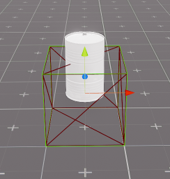
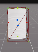
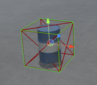
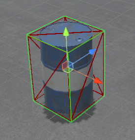
In this example is shown a Static element where a barrel has been assigned as model. In the first image we see how the barrel is smaller than the physic shape (represented by a red cube), then adjusting the Physic Scale property we are able to set the physic shape of the component, and then the model fits according their shape. Also, the Model Scale, Rotation and Position could be changed to get the same objective:


Instead to assign a model, you can assign a Component from the Models Library:
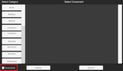
The components have their own collision shape and physics, when in a Static, Dynamic or WorkPart element is assigned a component from model’s gallery, this will adapt their shape to the component itself, losing their own shape:
- This WorkPart has the default shape:
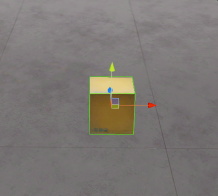
- When a component is assigned:
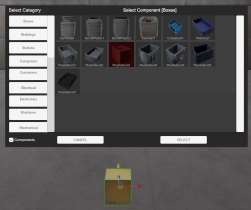
- The WorkPart will have the shape of the component (not necessary to fit in like the model):