Graphic Code & Controllers
Controllers
The Controllers are the tools for the Components in order to give it special behaviors, each component has their own controllers. The Controllers avoid writing code and simplifies the machine.
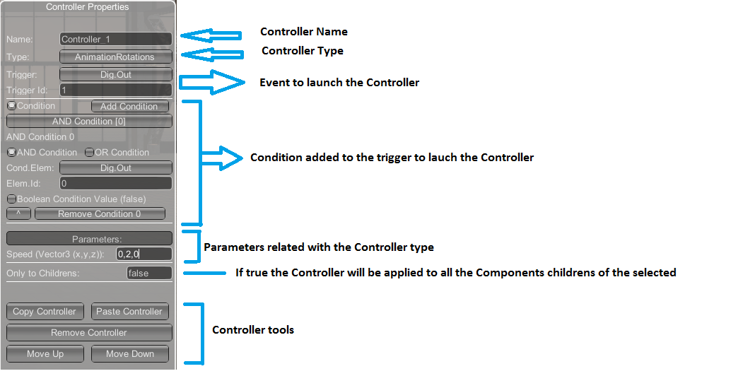
Use it to activate the special components functions without using script code in the Machine Script Code.
Graphic Code
The Graphic Code allows to program the machine behavior without writing C# code. Useful for all the users who do not have programming knowledge. Using this tool, you will be able to create an automatic system to automate without writing any line of code. Each component has different graphic blocks associated with it that allow you to perform actions on it in a totally graphic way without the use of code.
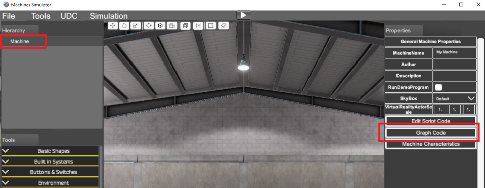
To start using the Graphic Code feature, click over the Machine and click the Graph Code Button:
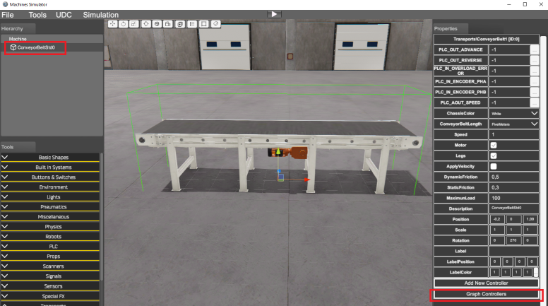
Or on each selected component, pressing the Graph Controller button in the right Property Grid:
Once pressed, the Graph Code editor will be launch:
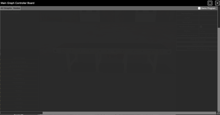
Now you can press right mouse button to show the context Node menu or press the upper Nodes menu to show all the available nodes for the current component.
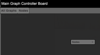
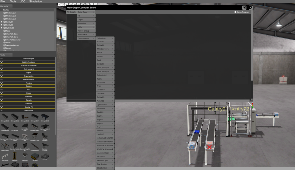
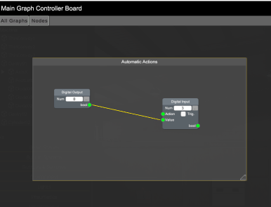
If the Graph Code editor is launched from the Machine component will allow the access to all the available components in the machine:
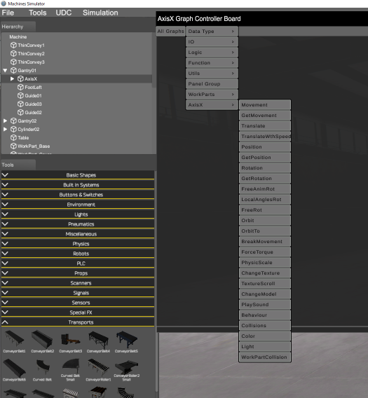
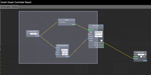
If the Graph editor is launched from any of the available components only will show the nodes for this selected component:
From the Machine Graph editor, you can toggle between the machine logic mode or the demo program mode by clicking in the Demo Program check located at the upper right side of the Graph Code window:
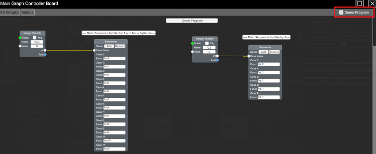
Using the Graph Code feature, when the machine will be in Run Mode, will execute always all the Graph code located in the Machine Graph Code window and in each Graph Code component. If the Machine is launched from the Machines Simulator main menu in Demo mode, will be executes the Graph code located in the Machine Graph Code window, the code in the Demo Program and in each Graph Code component. (This is different from Script Code, due in Demo mode only will be executed the code in the Machine Demo Script Code and not in the Machine Script Code).
Once in the Graph editor use the following mouse buttons:
- Mouse Wheel: zoom in/out
- Mouse Wheel (or mouse middle button): press and move the mouse to pan the graph code (left-right-up-down).
Once a node in placed in the Graph, click over it to move it to the desired position. Pressing left mouse button over an empty code area and drag it, will show the selection tool to select the desired nodes:
Node Types
The nodes are the tool that allows programming, each one of them has different functions and by making the connections between them we can achieve the desired operation. There are the following types of nodes:
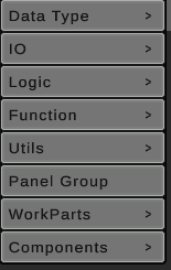
- Data Type: Allows to insert different data types for variables and/or constant values. The types are:
- Boolean (true or false value)
- Integer (numeric value with no decimal values)
- Float (numeric value with decimals)
- String (text value)
- Vector3 (three numerical values with decimals, usually used for positions in space)
- Data Converter: especial function to convert between different value types.
- IO: Allows to declare the analog and digital Inputs and outputs, in normal mode the Outputs only can be read and Inputs can be read and write. In Graph Code Demo program both Inputs and Outputs can be read & written.
- Logic: Allows to write nodes for logic Boolean operations:
And,Or,NotandXor. - Functions: the following functions are available:
- Branch: checks if the input value, if is true, the first output is active, if false the second.
- Compare: makes the selected comparation operation, the result will be true or false.
- Formula: for complex requirements allows to write an expression with different input parameters and one output parameter.
- New Function: allow to insert a new function to be called by the Function Call node.
- Function Call: when the input is true calls the typed function (only available in Machine Graph).
- Sequencer: makes a Switch Case function to sequence Functions according the integer input variable.
- Init: active only once at system startup, useful to initialize variables or functions.
- Math: performs the selected mathematical operations on the two input parameters and returns it for the output parameter.
- Maths Operation: performs the selected mathematical operations on input parameters and returns it for the output parameter.
- Math vector3: performs the selected mathematical operations on the Vector3 input parameter and returns it for the Vector3 output parameter.
- Switch Case: If the input parameter is true activates the corresponding output.
- Timer: sets/resets a timer, when the timer is reached activates the output.
- Trigger: triggers the input variable, the output will be on only in the first change of the input parameter.
- Utils:
- Delta Time: returns a compensation factor so that movements do not depend on the speed of the system.
- KeyPress: returns true if the selected keys are pressed, maintained or released.
- Mouse: gets information about the mouse buttons and position.
- Message: shows different types of messages in the screen.
- Model: returns the selected 3D model from the model gallery.
- Texture: returns the selected texture from the texture gallery.
- Sound: returns the selected sound from the sound gallery.
- Comment: inserts a comment in the graph.
- Panel Group: panel to group nodes. Used to make nodes groups (designed to a same functionality) that could be moved maximized or minimized. Make double click in the Panel Caption to change the name.
-
WorkParts: these nodes can be used to managed and interact with the current parts present in the machine, the available nodes are:
- WorkPartType: returns the input WorkPart type.
- WP Model: changes the 3D model (with scale, position and rotation) for the input WorkPart.
- WP Scale: changes the WP Scale for the input Wp.
- WP texture: changes the texture (and tile) for the input WP.
- WorkPartColl Ray: returns the WP that collides with the ray with origin and direction passed as input parameters.
- WP Contact: Returns the WP that is in contact with the passed WP.
- WP Attach: attaches the two passed WP.
- WP Detach: if the passed WP has other WP attached, the detaches it.
- WP Insert: inserts the second WP passed in the first passed WP.
- WP Release: if the passed WP has other WP inserted, releases it.
-
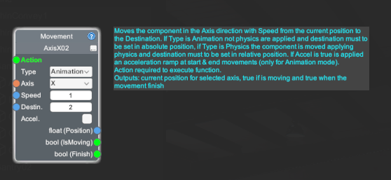
Components: For each component the machine has in their hierarchy, appears in this menu, in order to be called to customize it. Each component node has a help icon located in the upper right side, if the mouse cursor is placed over it, it shows a text about the node functionality:
Nodes layout
All the nodes have similar layout with the following properties:
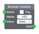
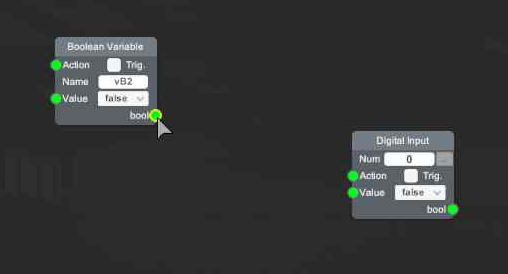
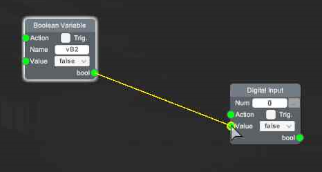
In the left side there are the Input ports, where the input condition must to be connected, in the right side there are the outputs ports that will outputs the values in function the node functionalities. To make the port nodes connection place the mouse over the desired port and once will be mark in yellow press left mouse button and drag over the desired node port:
You have to be in mind that:
- Only is possible to make connections between ports of different type (outputs ports with inputs ports and input ports with output ports). Not possible to make connections between same type ports (inputs ports with input ports and output ports with output ports).
- The output ports can have multiple connections, inputs nodes can have only ONE connection.
- Only is possible to make connections with ports of same data type, these data types have different colors in order to identify quickly, these are:
- Boolean Ports (green):

- Int Ports (white):

- Float Ports (blue):

- String Ports (orange):

- Vector3 Ports (yellow):

- WorkParts Ports (magenta):

- Boolean Ports (green):
Graph Code Program Structure
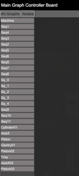
Due a machine can be composed by a lot of components and each one can have a Graph Code associated or not, in order to quickly locate the Graph Code for each programmed component, you can use the function to display all the elements that have Graph Code programmed in the machine, for this, click on the top menu All Graphs, then a list will be displayed in the Left side with all the components that have Graph Code programmed, and by clicking on each item you can quickly view its code.
Graph Code Programming Strategies
As a development tool, there are many ways to program using the graphic code, but the recommendation would be:
- Use the Graph Code of the Machine Object to manage all the logic that involves all the relationships with the available components in the machine.
- Use the Graph Code of each component to manage individually the logic of this component isolated from others.