Physics & Joints
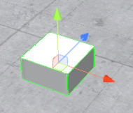
1. Hinge Joint
This special component has not a representation in the machine. Serves to joint two Dynamic Elements or one Dynamic Element with one Static Element.
Next are listed the properties of this element:
- Body Source: Id of the source element (element attached to).
- Connected Body: Id of the connected body (element who is attached).
- Anchor: The position of the axis around which the body swings.
- Axis: The direction of the axis around which the body swings.
- Auto Configure Connected Anchor: If this is enabled, then the Connected Anchor position will be calculated automatically to match the global position of the anchor property.
- Connected Anchor: Manual configuration of the connected anchor position.
- Use Spring: Spring makes the Rigidbody reach for a specific angle compared to its connected body.
- Spring: Properties of the Spring that are used if Use Spring is enabled.
- Spring: the force the object asserts to move into the position.
- Damper: The higher this value, the more the object will slow down.
- Target Position: Target angle of the spring. The spring pulls towards this angle measured in degrees.
- Use Motor: The motor makes the object spin around. Properties of the Motor that are used if Use Motor is enabled.
- Target Velocity: The speed the object tries to attain.
- Force: The force applied in order to attain the speed.
- Free Spin: If enabled, the motor is never used to brake the spinning, only accelerate it.
- Use Limits: If enabled, the angle of the hinge will be restricted within the Min & Max values. Properties of the Limits that are used if Use Limits is enabled:
- Min: The lowest angle the rotation can go.
- Max: The highest angle the rotation can go.
- Bounciness: How much the object bounces when it hits the minimum or maximum stop limit.
- Contact Distance: Within the contact distance from the limit contacts will persist in order to avoid jitter.
- Break Force: The force that needs to be applied for this joint to break.
- Break Torque: The torque that needs to be applied for this joint to break.
- Enable Collision: When checked, this enables collisions between bodies connected with a joint.
- Enable Pre-processing: Disabling pre-processing helps to stabilize impossible-to-fulfil configurations.
2. Hook
This component serves to join WorkParts that are in contact with this component when the PLC output defined in the property PLC_OUT_TAKE is on. The plc input PLC_INP_DETECTED will be activated to inform that the hook component is in touch with the WorkPart.
- Use the Multiple property to true to catch more than one WorkPart at once.
- Use the ForceWorkPartPosition property to force the position of the WorkPart at the component position.
- Use the PartTakedCollisions property to true if you want the taken WorkParts will collide with components, if is set to false, the taken WorkParts will not collide with other components.
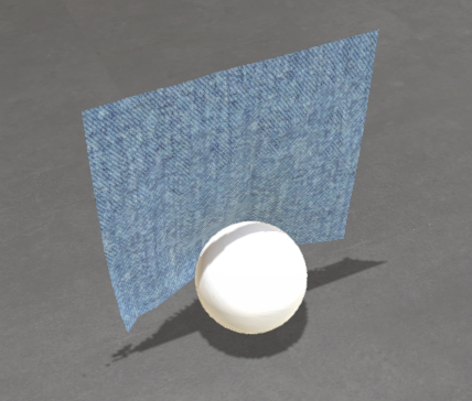
3. Cloth
Use this component to simulate cloth material. Texture and behavior can be customized. This component only collides with Sphere or Capsule shapes.
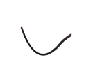
4. Cable
The cable component simulates the behavior of a physical cable connected at two ends. Endpoints can be user-configured fixed points or can be associated with other components such as Static Element, Dynamic Element, or Plane Element.
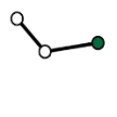
5. Inverse Kinematics
Using this component, you can create complex mechanical systems that will move in a hierarchy node structure following a selected target. Inverse kinematics is the mathematical process of calculating the variable joint parameters needed to place the end of a kinematic chain, such as a robot manipulator or any kind of mechanical skeleton, in a given position and orientation relative to the start of the chain.
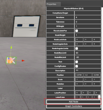
The Inverse Kinematic component can be configured (for each node) with the following properties in order to have the desired behavior:
- ComponentNameTarget: sets the component name that will be the target of the IK Chain. The last node of the IK chain will try to reach the target position. Set this property empty if the target will be set by script code.
- Iterations: 4 by default, here you can program the number of iterations the algorithm will make to reach the target position.
- Tolerance: the algorithm tolerance to reach the target position.
- IKWeight: the general weight of all the IK nodes to reach the target (1 maximum, 0 none).
- NodeWeight: the weight this node will have in the general chain (1 maximum, 0 none).
- Recalculate Pos: check this property to recalculate positions for each loop.
- NodeLockAxis: locks one of the three axis (X,Y or Z) to rotate around.
- NodeAngularAxis: selects one of the three axis (X,Y or Z) to rotate around to reach the target position.
- NodeAngularLimits: check this property if the rotation axis has limits to rotate around.
- NodeMaxLimit / NodeMinLimit: sets the maximum/minimum rotation angle for the NodeAngularAxis selected (
NodeAngularLimitsmust to be set on). - Test: check to true to test the IK chain movement. When is set to true the Editor will set the focus on the component set as target in order to move it using the gizmos and check the behavior.
- Config Routes: enable this property to move the IK Chain to predefined target positions. These positions will be available when the simulation is running.
To create a new node press the Add Node button in the IK property grid:
There is a new User Defined component called Delta Robot that uses three of these components for each Robot arm:
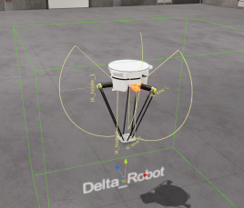
You can open this UDC to see how is programmed for a real application.
6. Inverse Kinematics for Robots
This component allows you to create robots with up to 10 degrees of freedom for angular axes. Each axis can rotate in one of three spatial positions (X, Y, or Z). It includes a path creation system with the ability to force each axis. Is possible to customize the IK algorithm using the following properties:
- SamplingDistance: The distance for sampling in the gradient descent algorithm.
- LearningRate: The rate at which the angles are adjusted during the gradient descent.
- DistanceThreshold: The threshold under which the arm is considered to have reached the target in terms of distance.
Press the Add Node button to add new angular axis. Each node (axis) can be configured:
- Axis: rotation in X, Y or Z
- Limits: check true if the rotation has angular limits
- Max Limit: maximum angular rotation value for the axis
- Min Limit: minimum angular rotation value for the axis.
Select Test property to true and start simulation to verify the angular movement of the IK component. Or check ConfigRoutes property to configure the routes for the Target of the IK component.
If CompNameTarget is empty the IK uses their own target system, or you can select a machine component to work as a target, then the last node of the IK chain will try to follow it.