Interfaces Configuration
Working with drivers SW/HW Interfaces Configuration
Machines Simulator 4 (MS4 in advance) can connect with a different number of hardware/software interfaces in order to be managed directly by means these interfaces. For instance, you can connect a Siemens PLC directly to the PLC where is running MS4 and using the Siemens PLC Driver manage the virtual machine directly form Siemens PLC without EasyPLC management. Or you can use the USB OPTO_RLY_88 or PhidgetsInterfaceKit cards to manage with external voltage (24Vdc) all the I/O used by Machines Simulator.
By default, when the machine starts, the connection is ready to be done with EasyPLC (Virtual PLC CPU).
To configure the driver interfaces
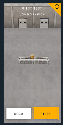
- Select the desired machine and press START Button.
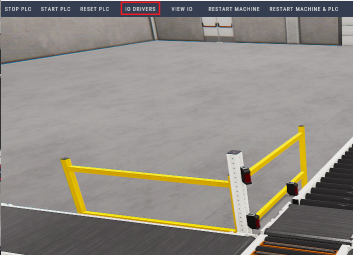
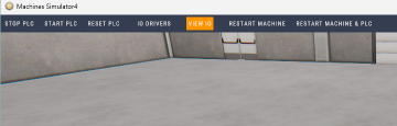
- Once the machine Starts, click on the IO Drivers button.
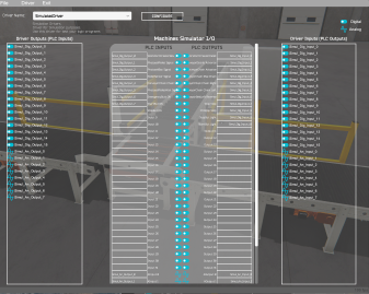
Once the IO Driver Configurator is launched, you will see this screen:
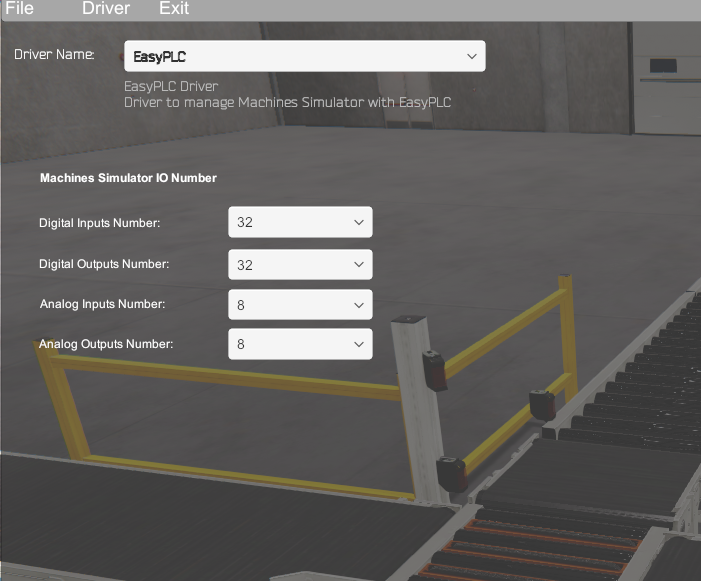
Driver Name: Select the driver to communicate Machines Simulator with (EasyPLC by default). Machines Simulator IO numbers: here are configured the IO digital & analog signal numbers used by the machine.
Available Drivers
- A1055S: driver for Yottacontrol A-1055S card.
- A1860: driver for Yottacontrol A-1860 card.
- Arduino Uno: you can use an Arduino UNO card to manage the Machines Simulator machines. Arduino UNO provides 12 configurable digital I/O (6 of them can be programmed as analogic output) and 6 analogic inputs.
- FactoryTalkLogixEchoDriver: Communicate with Rockwell FactoryTalk Logix Echo for ControlLogix 5580 controllers in simulation mode.
- IOIO_OTG: Allows to manage a IOIO OTG card. Provides 46 digital I/O (3,3V).
- ModBus: using this driver is possible to communicate with external devices using the ModBus protocol. This driver accepts the Modbus serial RS-232 (RTU) and TCP/IP protocols.
- Nirtec USB 15I16O: Driver to communicate with Nirtec_USB_1516 card.
- OPC Driver: using this driver will be possible to communicate with Real or Simulated PLC’s using the standard OPC protocol specifications.
- OPC Enhanced Driver: OPC driver enhanced to communicate with: Rockwell RSLogix OPC Server, OPC.SimaticNET and Mitsubishi MX OPC 6.
- OPC UA: PC Unified Architecture (OPC UA) is a machine-to-machine communication protocol for industrial automation.
- PhidgetsInterfaceKit: Driver to communicate with Phidgtes PhidgetsInterfaceKit I/O cards via USB port.
- PoKeys57U: This driver allows to manage a Pokeys57 interface USB card. Provides 55 digital I/O (5V tolerant), 7 analog inputs (12-bit).
- Remote Panel: Use an Android based Tablet or smartphone to communicate with Machines Simulator and manage remotely the I/O with a Virtual Panel Interface.
- Serial Driver: This driver provides 8 inputs and 8 outputs, sending/receiving only one byte in binary mode.
- SharedMemory: Use the API Windows FileMapping functions in order to create your own I/O driver with your favorite programming language.
- Siemens Logo: Communication Driver between Siemens LOGO (CPU's 0BA7/0BA8) and Machines Simulator via Ethernet protocol.
- Siemens_PLC: Communication Driver between Siemens PLC's (series 300/400/WinAC/1200/1500) and Machines Simulator via Ethernet protocol.
- SimulatedDriver: Driver for Simulation purposes.
- TPC IP Client / Server: Driver to communicate via TCP/IP protocol (client or server mode).
- TCP IP HTML Server: Driver to communicate via TCP/IP HTML protocol.
- TwinCAT: Use this driver for communication with TwinCAT v3 software.
- USB OPTO RLY 88: Driver to manage the USB OPTO RLY88 card.
- Virtual Panel: virtual panel console with lights, push buttons and selectors to write and see the logic state of the I/O.
How to configure a driver
Select the desired driver form the drop-down list and press the Configure Button:
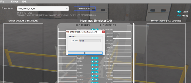
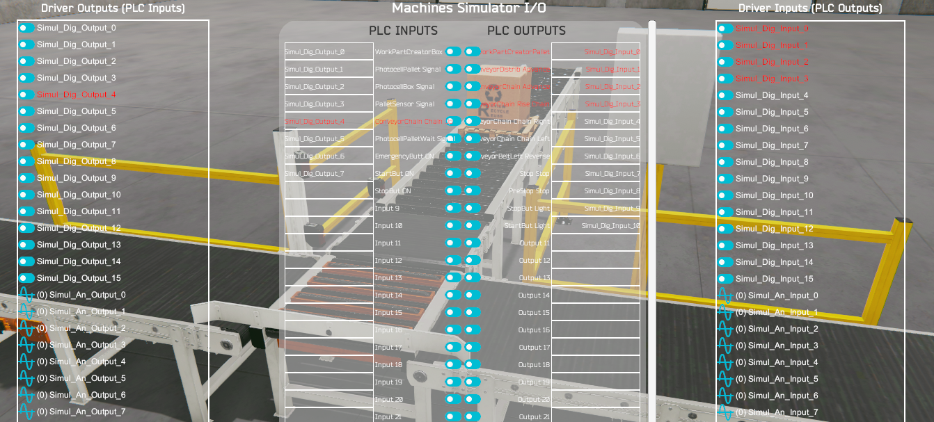
Depending on the driver type, a configuration window will appear to parameterize the selected driver. Once confirmed the driver I/O signals will appear in the left and right sides:
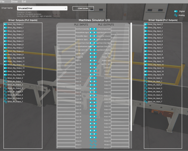
Now drag & drop the driver outputs (belonging to the PLC Inputs) in the Machines Simulator PLC Inputs (left side) and the drivers Inputs (belonging to the PLC Outputs) to the Machines Simulator PLC Outputs (right side).
- The digital signals are marked with the icon:

- The analog signals (numeric floating values) with the icon:

- Only digital Driver Outputs can be dragged in the MS digital PLC Inputs.
- Only analog Driver Outputs can be dragged in the MS analog PLC Inputs.
- Only digital Driver Inputs can be dragged in the MS digital PLC Outputs.
- Only analog Driver Inputs can be dragged in the MS analog PLC Outputs.
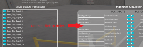
Delete Assignments
To delete one I/O assignment, make mouse double click over the Machines Simulator cell signal, or you can overwrite with other signal making drag & drop with the new one.
Automatic Assignment
If you want to automatically make the assignment between the driver I/O signals and Machines Simulator, press the menu Option Driver -> Automatic Assignment.
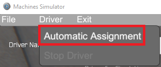
Then all the signals will be assigned automatically in a sequential way.
- driver output 0 with MS input 0, driver output 1 with MS input 1,…, driver output n with MS input n
- driver input 0 with MS output 0, driver input 1 with MS output 1,…, driver input n with MS output n
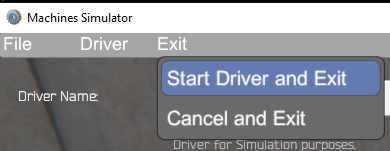
Once the configuration is done, select from upper menu Exit -> Start Driver and Exit, then the driver will be activated to communicate with the selected SW/HW device.
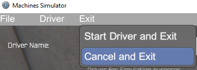
In case you do not want to make changes or modifications select Exit -> Cancel and Exit.
Save & load a driver configuration
Once a driver was configured and the I/O assignment between the driver and Machines Simulator has been done, is possible to save this configuration to later use it again without having to repeat the configuration process.
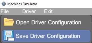
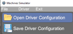
To do it, once you have configured the driver and the I/O assignment between the driver and Machines Simulator is done, select form menu File -> Save Driver Configuration.
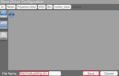
The Save Driver Configuration window appears, then type a name to save the configuration (the extension must be .drv) and Press Save Button.
To load a driver configuration already saved, select from menu File -> Open Driver Configuration.
From Load driver Configuration window, select the desired file:
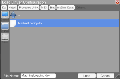
Then press Load Button and the driver configuration and driver I/O assignment with Machines Simulator will be loaded:
Now press from Menu Exit -> Start Driver and Exit to apply changes and start the communication with the driver and Machines Simulator.
If the driver has been configured correctly, a led indicator will light up green; if not, it will be displayed in gray color.

Test The Driver I/O when running Machines Simulator
If you want to see the driver and Machines Simulator signals when the machine is working, press again the IO Drivers button when the Driver is connected. The led located in the left button side indicates the driver is connected.
In red are shown the active signals:
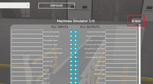
To change the IO digital & analog number used by Machines Simulator, press the IO Num button located at the upper right side of the Machines Simulator IO List.
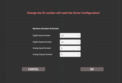
Select from the drop-down list the IO number desired to be used by Machines Simulator and press OK. Press Cancel if you don’t want to make any change.
Changing the Machines Simulator IO number will reset the current driver configuration and will be necessary to configure again if has been done previously to change the Machines Simulator IO number!
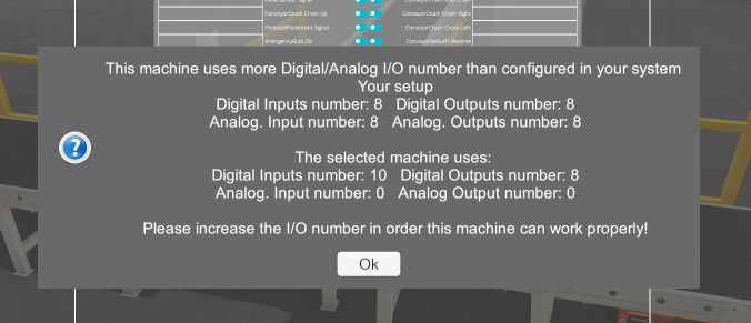
If the selected IO number are less that the used by the current select machine a warning message will appear indicating the minimum number of IO that must to be configured in order the machine can work properly.