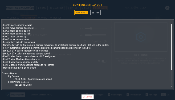
Keyboard Layout (Machines Simulator)
- Key W: move camera forward
- Key S: move camera backward
- Key A: move camera to left
- Key D: move camera to right
- Key Z: move camera up
- Key C: move camera down
- Escape Key: exits from current machine.
- Numeric keys (1 to 9): automatic camera movement to predefined camera positions (defined in the Editor)
- 0 Key: automatic camera trip over the predefined camera positions (defined in the Editor)
- (W, S, A, D) + Space: increases camera speed
- (W, S, A, D) + Left Shift: reduces camera speed
- Key F1: view/hide actuators/sensors I/IO assignment
- Key F3: view/hide components label
- Key F4: commutes between fly camera and 3D camera modes
- Key F5: toggle from windowed screen to full screen
- Key F9: toggle to Pause/Normal mode
- Key F10: Start/Stop recording a video of the machine
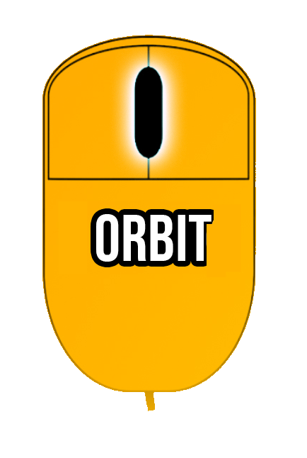
- Mouse Right Button: Look around
Camera Modes:
-
Fly Camera: -
(W, S, A, D) + Space:increases speed -Left Alt Key + Mouse:camera Orbit mode -
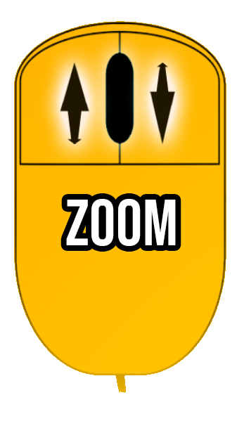
3D Camera: moves the camera as most popular 3D designing software’s, using only the mouse. Middle mouse button rotates the camera, right mouse button pans the camera, mouse wheel zoom int/out (+ left Shift key to reduce speed and increase accuracy).
-
First Person Camera: -
Key Space:Jump Use the mouse to move free for the 3D word, click right mouse button and use the mouse to move the camera in left-right, up-down and combining with the W,S,A,D keys you will be able to move in a fly style camera. When the cursor is over a movable or interactive object, the mouse cursor will change, pressing the left button the object can be moved by the user to interact with the system, use mouse wheel to approach or move away (press left control to block parts in air, then rotations are not allowed). -
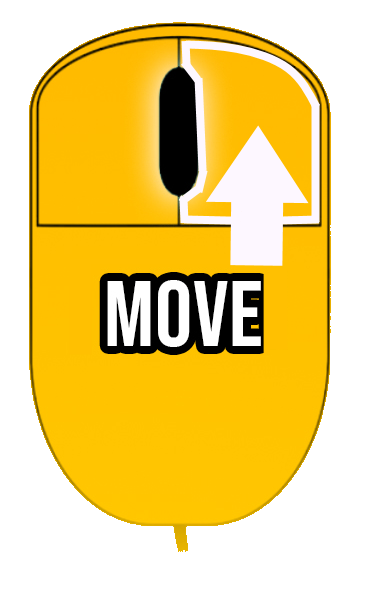
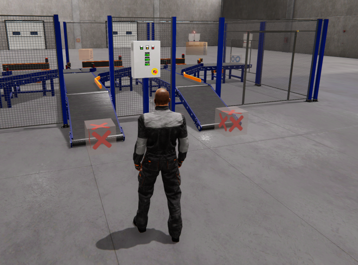
Third Person Camera: in this camera mode an operator is controlled to simulate human interactions with the simulation, use the mouse to rotate the camera, W-S-A-D keys to move operator, left mouse button to Zoom view + right mouse to interact with buttons & WorkParts. Left Shift key to run, and Numeric Keypad Plus and Minus keys to change operator scale. C key to crouch and Space key to Jump.
Camera Orbit Mode
In camera Fly Mode press left Alt key to use the camera orbit mode, move the mouse to rotate camera around the white central point showed in the screen
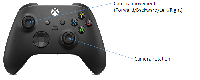
Joystick
Machines Simulator Interface
When Machines Simulator starts, different pages are available, here is their description:
Home Page
This is the start page, here you can see the software features, news and the social information to be updated about the software information:
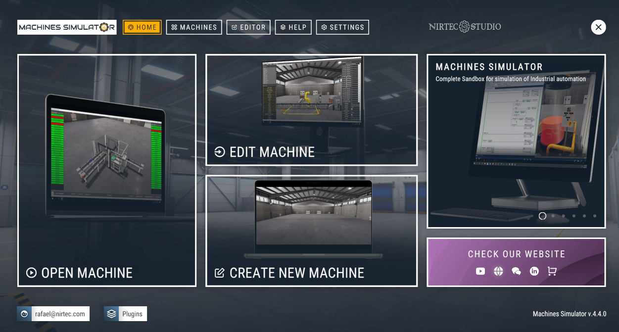
From Home page you'll have access to Nirtec's various information channels to stay informed about the latest news, tutorials, and more:
Click on YouTube icon to access our YouTube Channel, where you will see our publications with very interesting news and tutorials:

Click in Web site icon to visit Nirtec web page: www.nirtec.com

Click in Forum icon to access the Nirtec Forum, there you will have free technical service:

Click on LinkedIn icon to acces our profile, there you will find our company news:

Finally click on the Nirtec Asset Store icon to access our store:

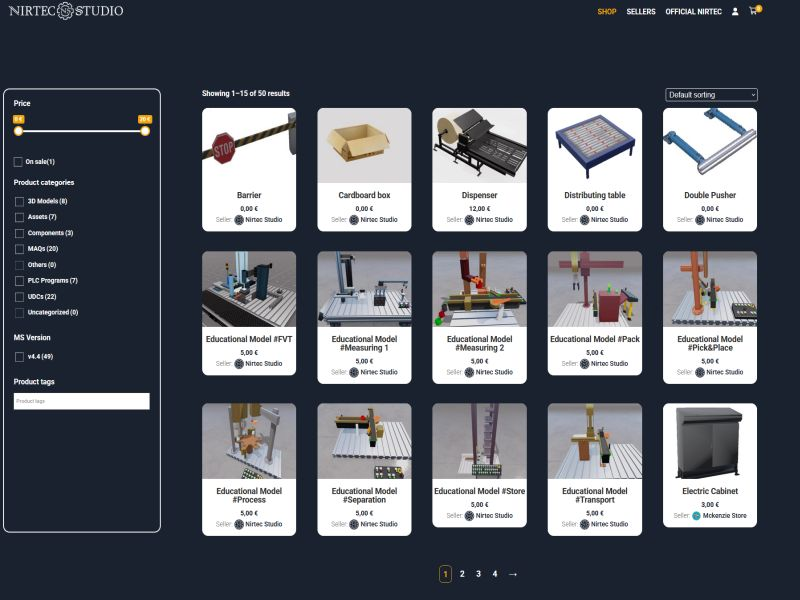
Nirtec Asset Store
Starting Machines Simulator v.4.4 the Nirtec Asset Store is now available. On this platform, you can download content designed for Machines Simulator, whether it's new machines, components, UDCs, 3D models, assets, or other related content such as PLC programs, automation tutorials, digital twins, etc. On the Nirtec Asset Store, you can download this content either for free or by purchasing paid items. Each user can create a seller account if they are interested in publishing content for purchase in the store or offering it for free. This will expand our industrial simulation and automation content to offer more specialized content in this sector.
If you're interested in creating a seller profile on the Nirtec Asset Store, you can check out the technical documentation in our forum post.
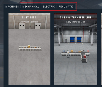
Machines
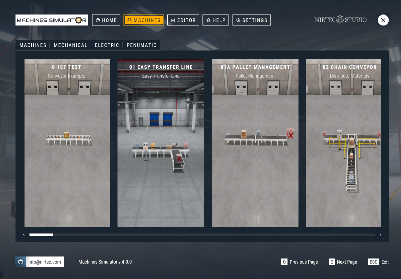
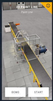
In this page you can select the systems to launch, click over the machine image to see their description, press DEMO in order to see how the machine could be operated, this is a help to know how you must to program the machine with the PLC (in this mode there is not communication with EasyPLC) and press START button lo launch machine to be test it with EasyPLC or any PLC system.
Each system has an objective and a difficult level, of course these systems can be programmed of thousand ways, and you can find other objectives that the proposed, in order to have different problems to solve. Here you have a tool to practice your programming knowledge, or to test PLC programs before to be loaded in the final system to avoid errors or mechanical damages.
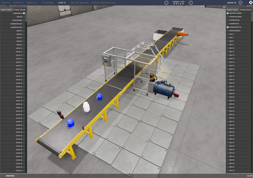
When the machine is launched, you will see in the lower side of the screen the PLC Panel, where are available the following functions:
- STOP PLC Button: stops the Virtual PLC (only enabled if there is communication with Virtual PLC).
- RESET PLC Button: resets the Virtual PLC (only enabled if Virtual PLC is in Stop mode).
- START PLC Button: set Virtual PLC in Run Mode (only enabled if Virtual PLC is in Stop mode).
VIEW IO Button: Shows the Digital I/O Window. Allows see and change the logic states of the digital Inputs and Outputs. Make click on any button to change the value. Useful for test and debug process.
- RESTART MACHINE Button: when is pressed restart the machine in their initial status.
- RESTART MACHINE & PLC Button: when is pressed restart the machine in their initial status and makes a PLC Stop (only enabled if Virtual PLC is in Stop mode).
You can simulate an input or output failure, making right click over an Input or Output button, then this signal will be disabled and will not attend to the machine input or output device. The button will change to yellow color when is disabled. Make right click again to enable it. This can be useful if you want to test what happen if a sensor (photocell, inductive switch or whatever) is broken and is not given signal to the PLC.
This Toolbar is very useful at the beginning of a machine programming; due is very frequently to debug the PLC program and is needed to start/reset/stop the PLC very often. These tools allow speeding the programmer work.

Interacting with Elements
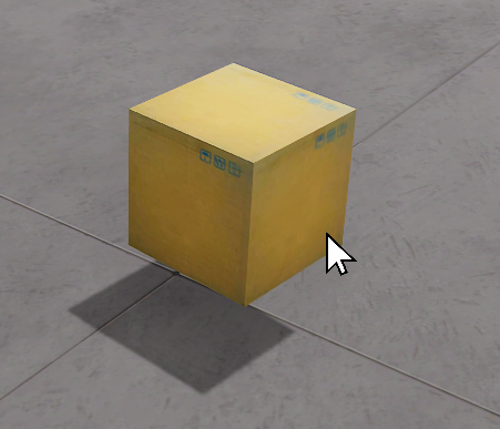
When the simulation is running, you can interact with all the parts that are moveable, as the WorkParts and Dynamic Parts (elements affected by the gravity), in this way you can test the machine behavior forcing unwanted situations or testing what would happen if the elements were moved in a different way than expected. To do it, place the mouse pointer over these elements then the mouse pointer will change, and pressing the mouse left button you can catch the elements and move it according your needs.
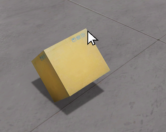
Press & maintain Left mouse button to catch elements and move them.
If you press the left control key before picking up an item, the item will move locked, that is, in the position it was in without any rotation.
Press & maintain Left mouse button + Left Control Key to catch elements without affecting gravity.
If the left control key is not pressed, the element will be dragged by exerting a force on the bearing point. Once you have one element picked, use mouse scroll wheel to zoom in/out.
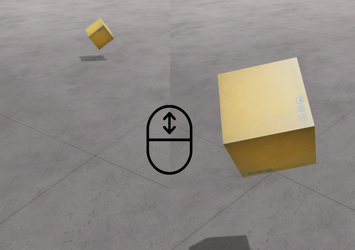
Use mouse wheel to make zoom in/out with the elements picked.
Simulation of I/O Errors
Using the View IO panel is possible to force typical errors of shorted inputs or outputs to zero or one, to do it, press with the mouse right button over the digital input or output you want to simulate the error, if you press once the I/O cell it will appear gray and simulate a short circuit to 0, therefore the signal will never be activated. If you press again, it will turn yellow simulating a short circuit to 1, so the signal will always be active. Press again to return to the normal state.
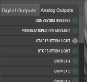
Pressing once, the signal will be always 0 and not will be activated (Gray Color).
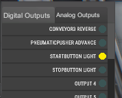
Pressing twice, the signal will be always 1 and will be activated (Yellow Color).
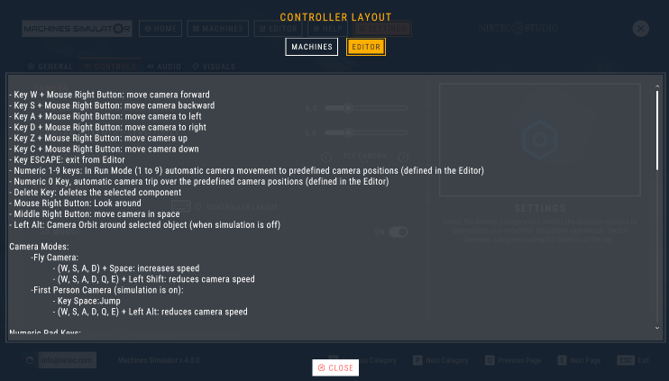
Editor
In Editor page can be launched the Machines Editor feature, use the editor to create your own machines. Five different environments are available:
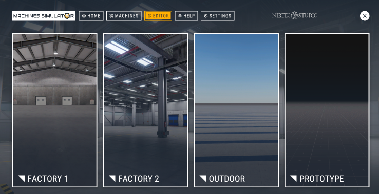
- Factory1: interior environment of a factory.
- Factory2: interior environment of a modern factory with exteriors
- Factory3: outside environment.
- Factory4: environment for prototyping, recommended for low resources computers (uses a low-profile illumination system with low graphic charge)
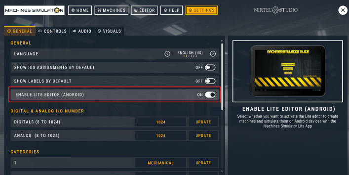
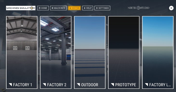
- Factory Lite: use this environment to create machines for Machine Simulator Lite (Android App). By default, is disabled, to activate it is necessary to enable it form Settings -> General:
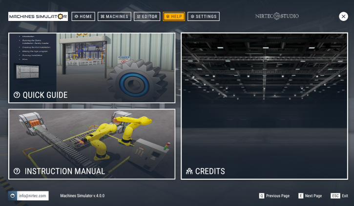
Help
Manual Guides & Information about the software
Settings
In settings page can be configured the general parameters, graphics, sound level and controls customization:
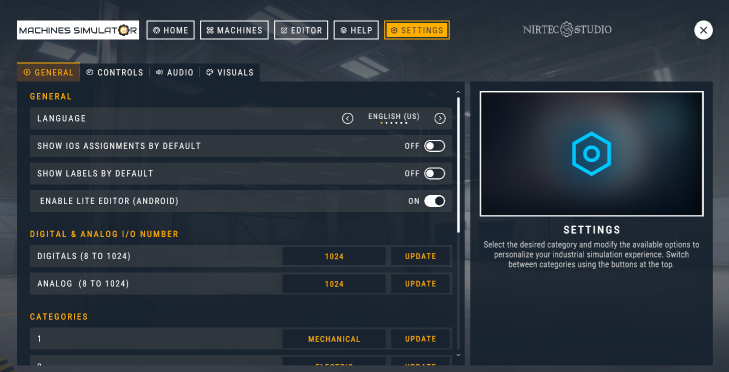
General:
- Language: the software is available in 6 languages: English, French, German, Italian, Portuguese and Spanish.
- Show IO’s Assignment by default: if selected when the simulation starts, appears the description for each component Input and Output (analog & digital).
- Show Labels by default: if selected the label for each component is shown.
- Enable Lite Editor (Android): if selected shows the editor for Machines Simulator Lite (Android App).
- Digital & Analog I/O Numbers: Sets the I/O digital & analog number to simulate (1 to 1024).
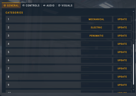
- Categories: Here you can set the descriptions for a maximum of 10 categories in order to category each of the created machines.
- Check Updates: Click the Check for Updates button to check if a new version is available for download.

Controls:
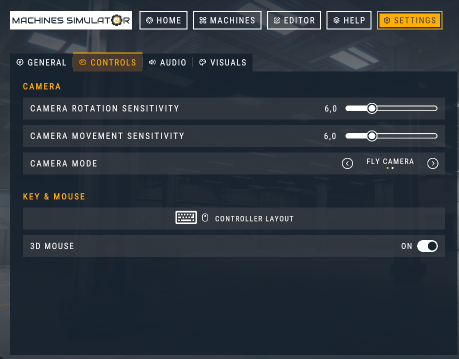
- Camera Rotation Sensibility: configure the default speed the camera will move using the mouse.
- Camera Movement Sensibility: configure the default speed the camera will move using the keyboard (W,A,S,D).
- Camera Mode: you can select between two camera modes, Fly camera or 3D camera. When the simulation starts, by default will be active the selected camera mode.
- Controller Layout Button: Show the keyboard & mouse mapping for the simulation and the editor.
- 3D Mouse: select this feature if you are using a 3D Connexion Space Mouse (if selected will be the default camera mode in the simulation and editor).
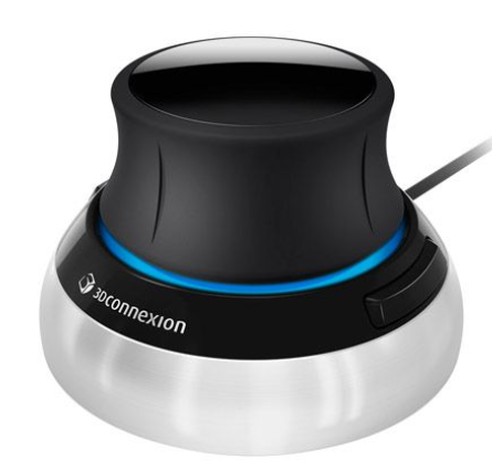
The 3dxWare package installs an emulator which basically lets the 3dconnexion device pretend that it is a game controller. However, this will cause problems in the Machines Simulator camera movements. So, you need to disable the KMJ emulator using these steps:
- Go to Device Manager
- Switch to View – Devices by Connection
- Under 3Dconnexion KMJ Emulator, look for HID-compliant game controller
- Right-click and disable it
It will no longer show up under Game Controllers in Windows and Machines Simulator will work correctly.
Audio:
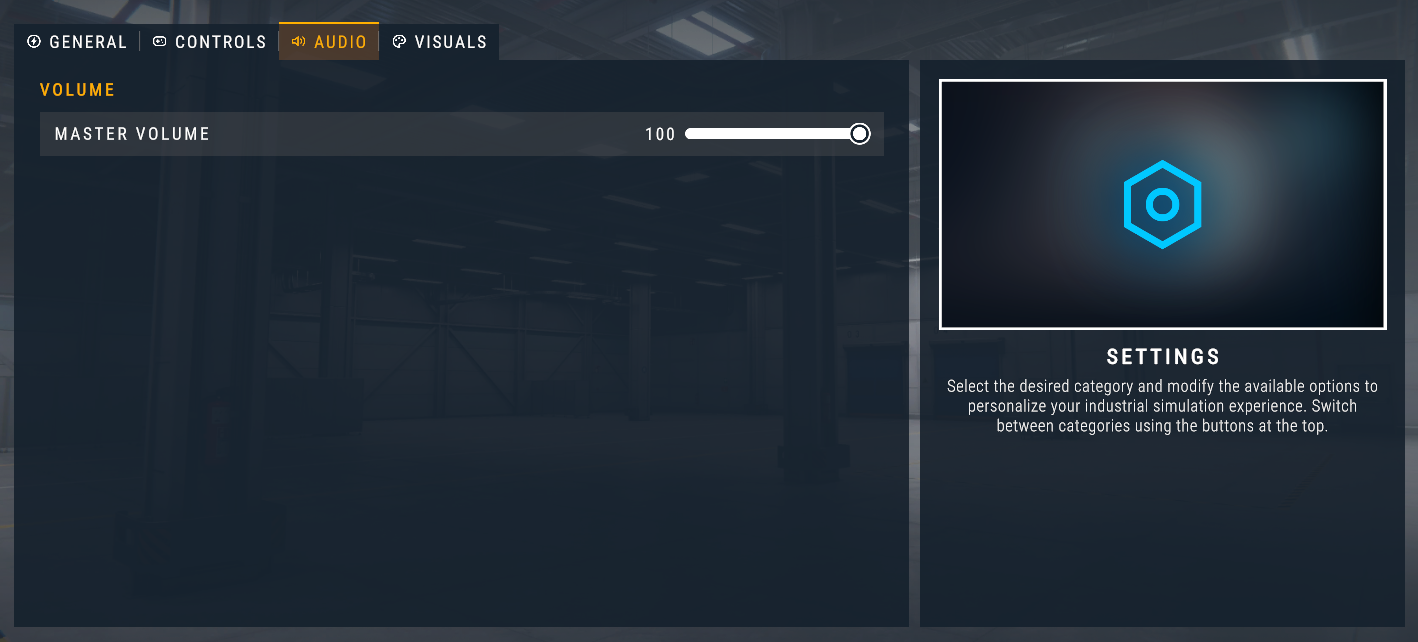
- Master Volume: sets the general volume of the sound.
Visuals:
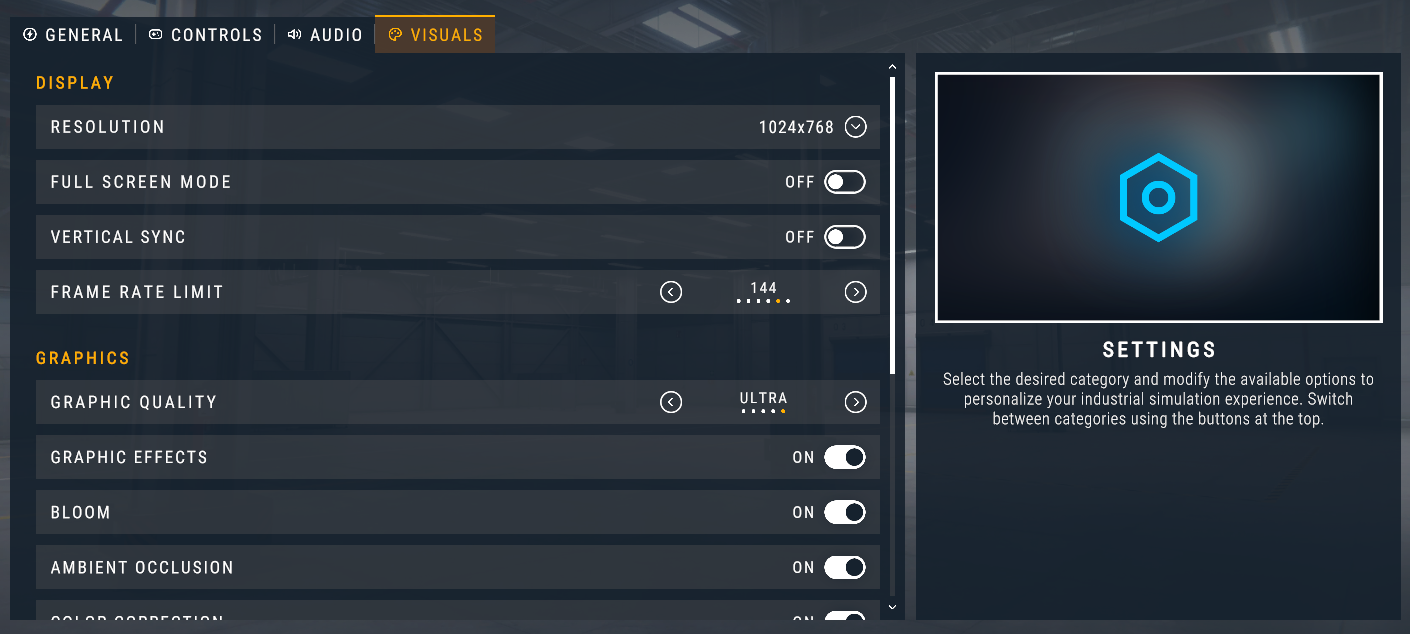
- Resolution: changes the screen resolution for the application.
- Full Screen: allows to run the application maximized in full screen or windowed.
- Vertical Sync: Synchronizes the application's frame rate with that of the monitor.
- Frame Rate Limit: Limit the frame rate. It is recommended to match this option with the refresh rate of your monitor. This option has no effect when Vertical Sync is enabled. If your PC makes a lot of noise due the cooling system, or you do not want to overload your CPU & GPU, you can decrease this value. You can also reduce it to conserve battery life on laptop computers. By default, the Frames Per Second (FPS) are not limited and will run as fast as your system can, but you can limit to 30, 60, 90, 144 or 240 FPS.
GRAPHICS:
-
Graphic Quality: there are 5 quality profiles predefined (Very Low, Low, Medium, High and Ultra). Choose the graphic quality according your computer resources (Very Low for a low resources PC and for a high-end computer).
-
Graphics Effects: Adds post process graphics effects, enhances the visualization but consumes more resources.
-
Bloom: Simulates glow and light effects.
-
Ambient Occlusion: simulates the soft shadows that occur in creases, holes and surfaces that are close each another.
-
Color Correction: improves color equalization generating more real environment.
-
Shadows: sets three profiles of shadows rendering, None (for low resources PCs), Medium, High or Ultra.
-
Antialiasing: gives a smoother appearance to graphics. Reduces the ladder effect in the different colors that come together in an image. Different settings indicate the number of samples per pixel. Values are 0 (no antialiasing), s, 4 and 8.
-
Anisotropic filtering: makes textures look better when viewed at a shallow angle, but it can be slower to process on the GPU.
-
Texture Quality: higher quality textures result in significant deeper details, but also requires more VRAM and video processing hardware.
In the case your computer has low resources (microprocessor, Graphics Card, RAM, …) and the simulations run very slow (FPS below 30) it is recommended to change the graphic settings according to the following example:
- Resolution: minimum possible that allows the correct display of the screen size.
- Vertical Sync: OFF
- Graphic Quality: Very Low
- Graphics Effects: OFF
- Bloom / Ambient Occlusion / Color Correction: OFF
- Shadows: None
- Anti-aliasing: X0
- Anisotropic filtering: Low
- Texture Quality: Very Low.
Camera Modes (In Editor Mode)
At the top right of the screen are located the camera control buttons. These controls allow managing the cameras with different behaviors:
- Fly Camera: the camera moves freely in the 3D world. Make click over the Fly camera button to commute between Normal Free Camera mode and Ghost Free Camera mode (in this mode there’s not collision with components, useful to place the camera in strategic points).


- 3D Camera: moves the camera as most popular 3D designing software’s, using only the mouse. Middle mouse button rotates the camera, right mouse button pans the camera, mouse wheel zoom int/out (+ left Shift key to reduce speed and increase accuracy).

- First Person Camera: moves the camera as a person, in this camera mode is not possible to fly (the Space key in this camera mode makes a jump action).

- Third Person Camera: in this camera mode an operator is controlled to simulate human interactions with the simulation, use the mouse to rotate the camera, W-S-A-D keys to move operator, Left mouse button to Zoom view + Right mouse to interact with buttons & WorkParts. Left Shift key to run, and Numeric Keypad Plus and Minus keys to change operator scale. C key to crouch and Space key to Jump.

- Travel Camera: the camera follows the configured path designed in the Editor.

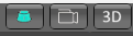
Camera change in Edit Mode (right upper corner):
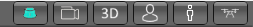
Camera change in Run Mode (right upper corner):
Time Speed Simulation
Making click over the Time Speed button, the time simulation can be change to slow or fast modes.

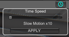
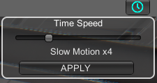
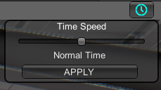
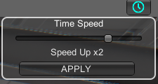
Click with mouse and move the slide bar to change the time speed. There are five positions to set the time speed to the following values:
- Slow Motion (10 times slower)
- Slow Motion (4 times slower)
- Normal time
- Speed Up (2 times faster)
- Speed Up (3 times faster)