Buttons & Switches
1. Press Buttons
Different kind of buttons are available:
- Emergency Button: Use this element to place a safety emergency Button in your machine, uses one PLC Input to inform about their state (pressed or not).

- Push Buttons: Uses one PLC Input to inform about their state (pressed or not) and one PLC Dig. Output to activate the button light.

- Led Indicator: a lamp that uses one PLC digital Output to enable/disable the light.

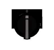
2. Selector
Selector with two or three configurable positions, uses two or three digital PLC inputs to inform about the current selector position.
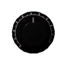
3. Potentiometer
Users can drag and rotate the potentiometer; one PLC analog input will inform about the current value (from 0 to 10 by default, but the maximum and minimum values can be customized, as the default starting value)
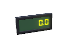
4. Digital Display
Shows numeric data using one PLC analog output or one PLC analogic input.
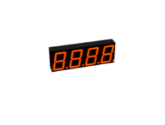
5. Display 7 Segments
This component manages a 4-digit display of 7 segments. You can program the behavior in BCD mode, then only are used the PLC Outs: PLC_OUT_A (as bit 0), PLC_OUT_B (as bit 1), PLC_OUT_C (as bit 2), PLC_OUT_D (as bit 4) and PLC_OUT_E (to activate decimal point). Or you can manage it directly activating/deactivating each segment using the corresponding PLC Out.
Use The multiplex to select the digit number desired using PLC_OUT_MULTIPLEX_BIT01 to activate the bit 1 and PLC_OUT_MULTIPLEX_BIT02 to activate the bit 2 in order to select one of the 4 display digits to set the value. It is necessary to set the PLC OUT Strobe once all the previous bits are configured to set the display value number.
Also is possible use one PLC Analog output to display its value (without the need to perform any conversion). You can configure the display color manually or use the PLC_Output_Color_Bit0 and PLC_Output_Color_Bit1 to select the display color, where 0: Red, 1: Yellow, 2: Green and 3: Blue.
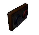
6. Switch
Two push buttons switch, each button can activate one PLC digital input.
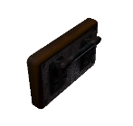
7. Lever Switch
A lever switch, activates one PLC digital input.
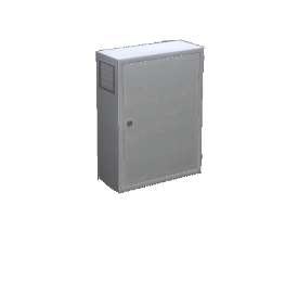
8. Electric Cabinet
This is a static element with a model property, useful to place all the previous components.