Introduction & Shortcuts
With Machines Simulator Editor, you can create your own systems with the machines and/or components available in the Editor library or you can create your own devices with the component Editor available inside the Machines Simulator Editor.
Machines Simulator Editor, hereinafter Machines Editor, is an easy-to-use tool, where you can create easy, medium or complex mechanical systems, with mechanical, electrical, electronic components assembled on it, to later be programmed with EasyPLC and check your ability in the PLC programming. In addition, you can replicate physical real systems to be programmed in a virtual way and avoid to damage the real system, or you can start programming and verifying your program BEFORE the system will be fabricated.
For this and much more reasons Machines Simulator & EasyPLC are a tool not only useful for students or beginners in PLC programming and automation, for the professionals can be a very appreciate tool.
With Machines Editor you can create a machine or a collection of machines or devices ready to work together or in a separately way, for this reason we call an ‘Installation’ a system created by Machines Editor, composed by different types of components.
Machines Simulator has two different work modes, Design Mode and Run Mode.
- In Design Mode, all the components are fixed on the screen placed in the position where the user has located it, the user can move the components with the gizmo system or Keypad numeric/cursor Keys, in this mode the physics engine of Machines Editor is stopped, you must use this mode to create your installation.
- In Run Mode, the physics system is running and the components will respond to gravity, and you can force the PLC outputs and see the PLC inputs to check the machine components behavior, in this mode it is not allowed to change the position or properties of the components. Use this mode to check the operation of your installation.
Keyboard Layout
- Key W + Mouse Right Button: move camera forward
- Key S + Mouse Right Button: move camera backward
- Key A + Mouse Right Button: move camera to left
- Key D + Mouse Right Button: move camera to right
- Key Z + Mouse Right Button: move camera up
- Key C + Mouse Right Button: move camera down
- Key ESCAPE: exit from Editor
- Numeric 1-9 keys: In Run Mode (1 to 9) automatic camera movement to predefined camera positions (defined in the Editor)
- Numeric 0 Key: automatic camera trip over the predefined camera positions (defined in the Editor)
- Delete Key: deletes the selected component
- Mouse Right Button: Look around
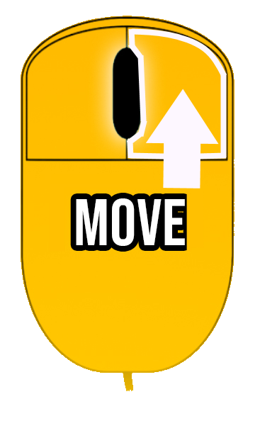
- Middle Button: move camera in space (Camera PAN up/down & left/right)
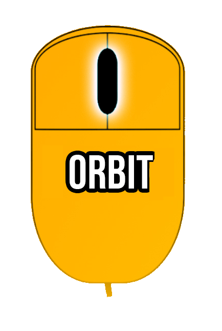
- Left Alt: Camera Orbit around selected object (when simulation is off)
- Left Control + Arrow Up: move item up in left hierarchy tree
- Left Control + Arrow Down: move item down in left hierarchy tree
- Left Control + Z: undo last position, rotation, scale operation.
- Left Control + X: redo last position, rotation, scale operation.
Camera Modes
- Fly Camera:
(W, S, A, D) + Space:increases speed(W, S, A, D, Q, E) + Left Shift:reduces camera speedLeft Alt Key + Mouse:Camera orbit mode.
- 3D Camera:
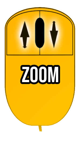
- Middle mouse button rotates/orbit the camera, right mouse button pans the camera, mouse wheel zoom int/out (+
Left Shiftkey to reduce speed and increase accuracy).
- Middle mouse button rotates/orbit the camera, right mouse button pans the camera, mouse wheel zoom int/out (+
- First Person Camera (only running the simulation):
Key Space:Jump(W, S, A, D, Q, E) + Left Alt:reduces camera speed
- Third Person Camera (only running the simulation):
- In this camera mode an operator is controlled to simulate human interactions with the simulation, use the mouse to rotate the camera,
W-S-A-Dkeys to move operator, left mouse button to Zoom view + right mouse to interact with buttons & WorkParts.Left Shiftkey to run, and Numeric KeypadPlusandMinuskeys to change operator scale.
- In this camera mode an operator is controlled to simulate human interactions with the simulation, use the mouse to rotate the camera,
Numeric Pad Keys
- 4: Move selected component to left
- 6: Move selected component to right
- 8: Move selected component to up
- 2: Move selected component to down
- 9: Move selected component to forward
- 1: Move selected component to backward
- 5: Rotate selected component in counter-clockwise
- 7: Rotate selected component in clockwise
Use the numeric Pad keys to place with accuracy the components that needs precise positioning. To do it with more precision, select the step mode pressing F2 key or click on the toolbar, grid mode button:

Function Keys
- Key F1: view/hide I/O list assignment
- Key F2: toggle the free/step mode selected component movement
- Key F3: view/hide components label
- Key F4: commutes between fly camera and 3D camera modes
- Key F5: toggle from windowed screen to full screen
- Key F9: toggle to Pause/Normal mode
- Key F10: Start/Stop recording a video of the machine
- Key F11: In Run mode saves a screenshot of the machine (to be shown in the machines selection menu)
- Key F12: Changes from STOP/RUN SIMULATION mode
Editor Gizmos
- Key W: Activates Translator tool
- Key E: Activates Rotation tool
- Key R: Activates Scale tool
- Key T: Activates the Scale Box
- Key Q: Deactivates tool
- Key L: Toggle between World/Local mode
- Key F: Camera is located in the selected component
- Left Control + Mouse Click: Multiselect components
- Left Control + Key D: Duplicate selected component
For Translation Tool:
- Key Z: Step Snapping
- Key V: Vertex Snapping
- Key Space: Surface placement
For Rotation Tool:
- Key Z: Step Snapping
For Scale Tool:
- Key Z: Step Snapping
- Key Z + Left Shift: Scale all axes
Copy / Paste Properties:
- Left Control + C: Copy the position, rotation and scale of the selected component.
- Left Control + W: Paste the position to the selected component.
- Left Control + E: Paste the rotation to the selected component.
- Left Control + R: Paste the scale to the selected component.
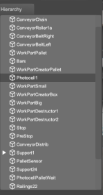
Hierarchy Reorganization
- Key Left Control + Up Arrow: move selected item up in the Hierarchy
- Key Left Control + Down Arrow: move selected item down in the Hierarchy
Use the mouse to move free for the 3D word, click right mouse button and use the mouse to move the camera in left-right, up-down and combining with the W, S, A, D keys you will be able to move in a fly style camera.
When the Editor is in RUN Mode (Simulation), press Left mouse button to take the WorkParts, and move mouse wheel to bring & move away the picked objects (press left control to block parts in air, then rotations are not allowed). In Edit Mode use mouse to select elements, when click over a component this will be selected.
Special Features
- Key Control + Key H: hides/shows the factory environment, or the floor in the outdoor environment.
Camera Orbit Mode
In camera Fly Mode press left Alt key to use the camera orbit mode, move the mouse to rotate camera around the selected component.
Orthographic Camera Mode
In order to use the orthographic camera mode, it is necessary to enter in 3D camera mode:
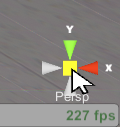
Once the 3D Camera is active, click in an empty space of the scene to remove the right property panel of the selected object, then the 3D Camera position gizmo will appear in the right bottom corner of the screen.
Click on the middle square to switch between perspective and orthogonal 3D camera modes:
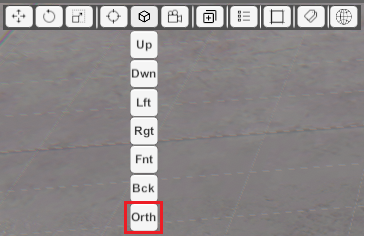
Once the camera is set to orthographic mode, you can click on each of the gizmo axis icons to set the camera in the desired position or you can use the Camera Positions icon from ToolBar in order to place the camera:
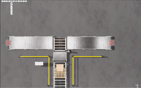
Or you can use the Orthographic camera mode clicking the Orth icon in the camera positions Icon tool from the ToolBar:
Making click on this icon, the camera will change to orthographic mode and top aerial view.