Interface & Menus
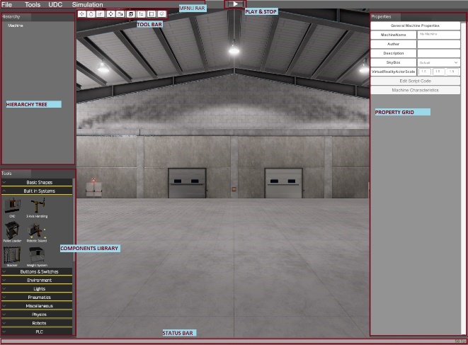
The Machines Editor Program Interface has the following components:
- Menu Bar: where are available the main program options.
- Tool Bar: here you can access the more used editing functions.
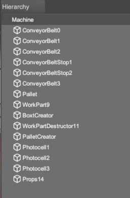
- Hierarchy Tree: where you find the components used by the machine, click it to select and edit.
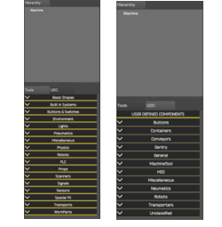
- Components Library: here you will find the components library used to create your machines.
- Property Grid: used to customize the current selected component.
- Status Bar: Here you find some important information about the program status and the current frames per second.
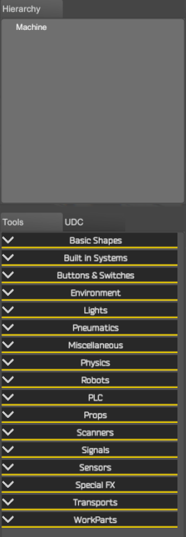
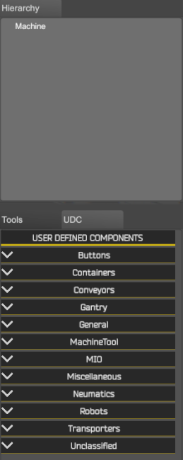
The Components Library is composed by two tabs:
- Tools: here are located the components library included with Machines Simulator.
- UDC: here are located the User Defined Components, these are the components that each user can make according to their needs, to later reuse them in the machines. By default, are included a lot of different UDC as reference for your own creations.
Menu Bar
The following items are available: File, Tools, UDC, Simulation.
File Menu
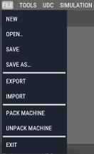
- New: creates a new machine.
- Open: opens a created machine.
- Save: saves the current machine.
- Save As: saves the current machine with a name defined by the user.
- Export: exports the selected components in the machine (
.exp) - Import: imports an exported machine file (
.exp) - Pack Machine: creates a packed machine with all the included assets this machine includes (UDCs, OBJ Models, textures, videos and DXF Files)
- UnPack Machine: load the packet machine and saves in the program folder structure all the used assets for this machine (UDCs, OBJ Models, textures, videos and DXF Files)
- Exit: exit from Machines Editor.
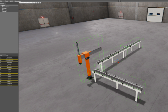
Export/Import Functions Starting version 3.20 a new feature is included, the possibility to export/import machine parts. To export a part of the machine, this means some of the machine components, left mouse click on each component located at the Machine Hierarchy upper left tree with left control key pressed:
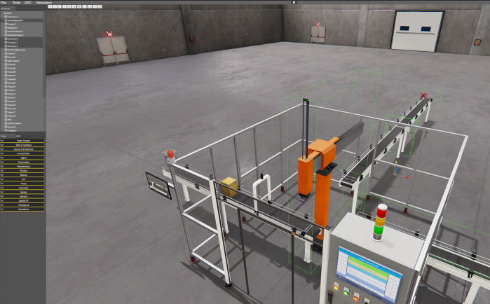
Then is possible to import in a new or other machine all the exported components:
Tool Menu
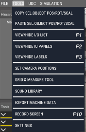
- Copy Selected Object Position/Rotation/Scale: when this option menu is pressed, is stored in memory a copy of the space data of the current selected component. The space data stores three Vector3 (three float numbers) data structure with the information of the position, rotation and scale of the component for each axis (X, Y, Z).
- Paste Selected Object Position/Rotation/Scale: when this option menu is pressed is showed a window where is possible to select the Vector3 data structure to be copied for each of the three axes:
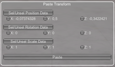
Press the buttons to select/unselect the different space properties (Position/Rotation/Scale), also you can click in each option to select the desired data axis. Clicking the Paste button will copy these data into the current selected component.
It is also possible to copy and paste positions, rotations and scales with keyboard shortcuts to perform the actions more quickly, to do this use the keyboard shortcuts to copy (Control + C) and paste position (Control + W), rotation (Control + E) and scale (Control + R).
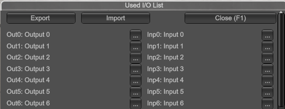
- View/Hide I/O List: use this tool to see/hide a windows list with the analogic/digital inputs/outputs used in your installations, using this tool you avoid to repeat used signals. Press Export button to export variables to file that can be import in EasyPLC or third party software’s. The data is exported in two files, one in INI format (with
.iosextension) and other in JSON format. It is also possible to import from an external file in.inior.jsonformat the number and descriptions of each of the descriptions of all analog and digital inputs and outputs. Press Import button and select the file containing the number and descriptions of the I/Os in the specific path.
- View/Hide IO Panels: use this tool to see/hide the panels with the digital input and outputs available for your machine, in the left side appears the digital outputs than can be changed by the user clicking over them, in the right side the digital inputs are shown and informs about the current status of the inputs (only read). This tool only is available in run mode.
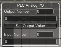
- View/Hide Analog I/O windows: use this tool to see/hide a windows list with the analogic inputs/outputs. Only used in run mode, is useful to simulate analogic outputs and read analogic inputs.
- View/Hide Labels: each component in your machine can have a label, use this label to show a descriptive text, with this tool you can show or hide the labels assigned to all components.
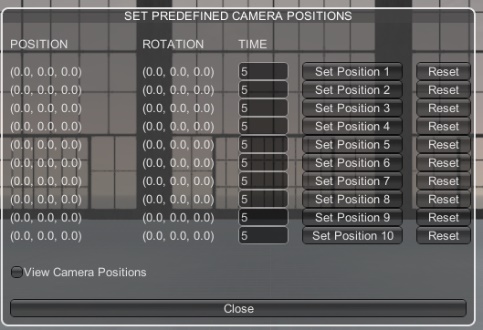
- Set Camera Positions: In the machine could be useful to place cameras in some ‘hot’ points to access quickly to it, with this utility we can do it very easy, when you are in the desired point seeing the desired objective, show this window and press over the Set Position X button to save the camera position and target. Later in Run Mode you can access to these positions pressing the ‘1’ to ‘9’ keys, you can save until 9 positions. Also exists an auto trip function, when you are in Run Mode, pressing the ‘0’ Key, the system will travel automatically by the defined points sequentially.
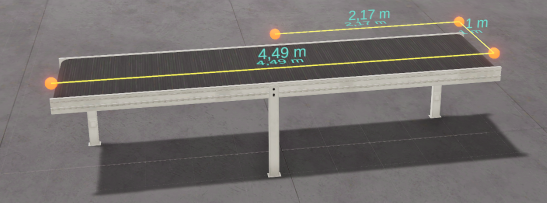
- Grid & Measure Tool: use this tool, available only in editor mode, to measure distances between components, moving each point using the mouse and configure the editor floor grid (changing the grid color and X & Z cells size). Move each point of the ruler using the position gizmos (X, Y, Z axes) or by clicking the mouse on the orange point and dragging.
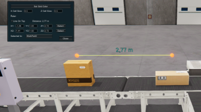
Press ‘V’ key while moving the selected ruler point with mouse to fix the ruler point to the collision face where the mouse pointer is touching. To create more measuring points, press left Control key + left mouse click over the ruler points.
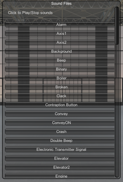
- Sound Library: Shows a list where all the available sounds are show and can be tested, you can use it in the script code.
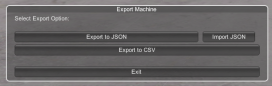
- Export Machine Data: this tool allows to export all the components designed in the machine in two selectable formats: JSON or CSV. The file includes the information related to each component, the relationships with the other components as well as labels, position, orientation and scale.
- Record Screen: select this function from menu or press F10 key during simulation to create a video of your machine. The video is saved in mp4 format.
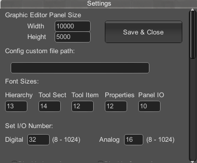
- Settings: From this menu, you can configure the following program parameters:
- The Graphic editor panel size to create programs in node graph language.
- A customized path where the machine files will be stored.
- The font sizes for the Editor and Simulation Panels.
- The number of digital and analog Inputs and outputs used by Machines Simulator.
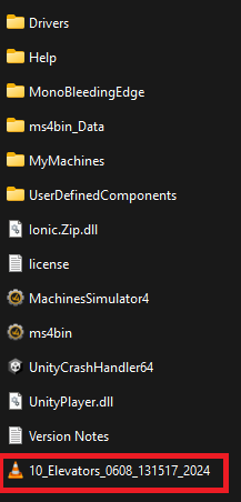
If you want to change the path where the program stores the files used by the simulation, take note you must to create four folders inside this folder:
Drivers\(here will be located all the drivers files)Help\(here will be located the help files)MyMachines\(here will be located the machine files .maq and their thumbnails images)UserDefinedComponents\(here will be located the UDC files .udc and their thumbnails images)
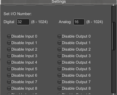
Set IO Number: Set the digital and analog Input and Outputs number available for the system. Also, here you can disable/enable the digital I/O in order to simulate I/O failures.
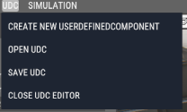
UDC Menu
It’s very difficult to provide all the machines, components, systems, devices needed to cover the entire users’ requirements. The solution is the Components Editor, where the users can create their own components and give the desired behavior to interact with the installation. These are the User Defined Components.
All the UDC can be shared with all the users. Visit www.nirtec.com web site to download new components.
- Create New UserDefinedComponent: creates a new UDC.
- Open UDC: opens a created UDC.
- Save UDC: saves current UDC.
- Close UDC: closes Component editor.
Simulation Menu
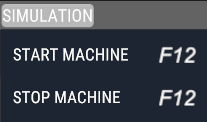
- Start Machine: starts the simulation (run mode)
- Stop Machine: stops the simulation (stop mode)
You can press F12 key to switch from stop mode to run mode and vice versa, or press Start/Stop button from menu bar.
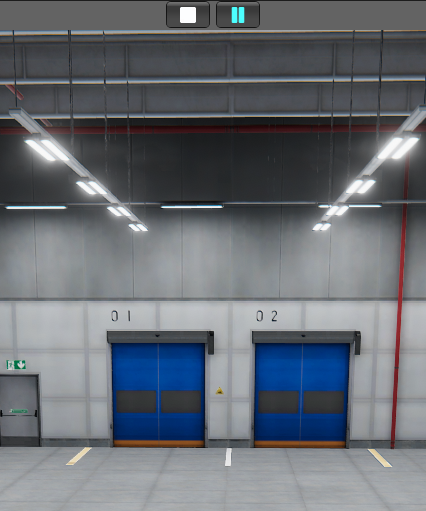
Press F9 or click on Pause icon to pause the simulation.
Editor Step Mode
If Step mode is selected, the components will be moved very slowly, useful to place the components with accuracy in the final position. You can toggle this mode on/off pressing the F2 key while working in the Editor. To move step by step the selected components using the mouse, press Z key and move the component translation gizmo.
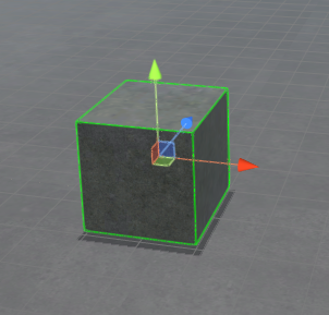
Gizmo Tool
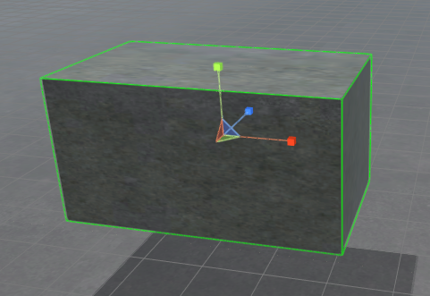
Once a component is created or selected, the Gizmo tool is showed in the center of the component. You can use this tool to move, rotate or scale the components.
By default, the translation Gizmo is selected. If you place the mouse over each axis arrow (red for X axis, green for Y axis and blue for Z axis), this will change to yellow color, then click and you can move the component moving the mouse. If you hold ‘Z’ key, the component will move step by step.
- Press E to change to the Gizmo Rotation Tool:
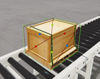
- Press R to change to the Gizmo Scale Tool:
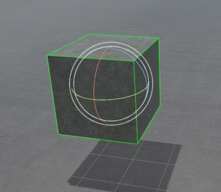
- Press T to change to the Gizmo Box Scale Tool:
- Press W to change to the Gizmo Translation Tool:
You can make the Undo and Redo operations on each component, selecting it and pressing Left Control Key + Z Key for Undo and Left Control Key + X for Redo.
Tool Bar

- Gizmo Position / Rotation / Scale / Box Scale: changes the current selected object gizmos.
- Focus: places the camera in the selected component, useful to locate elements (same pressing F key).
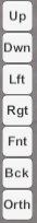
- Camera positions: Up, Down, Left, Right, front, back and orthographic.
- Reset Camera: reset the camera position and orientation.
- Duplicate: duplicates the current selected component (
Control + D). - I/O List: Shows/hides the digital Input & Output list (
F1). - Grid Mode: changes grid mode to on/off (
F2). - Components Label: show/hides the component labels (
F3). - Toggle Global/Local mode: useful to change rotation relative to the world or locally.
Hierarchy Tree
Here is show all the available components in the machine. Click on each to select and view/edit their properties. Hold Left Control Key to multiselect components.
You can reorder the components in the tree pressing the left control Key + Up Arrow to move item up or left control Key + Down Arrow to move item down.
Components Tree
Here you find the available Components classified in categories. To place a component in the machine, click over the desired Category to display the list and only is necessary to make click on it, then will be added to the machine.
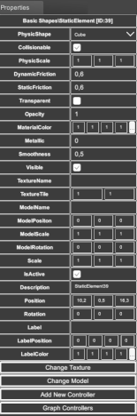
Property Grid
Once an element is created or selected, you can change their properties selecting them in the Properties grid. Here you can find all the available component properties.