Scanners
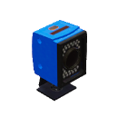
1. Camera
It is used to detect the WorkPart type that is present on the camera target, uses one PLC output that is the command to start to work and one PLC analogic input where will be written the workpart type detected by the camera. The detection field can be customizable.

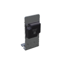
2. RFID Sensor
Used to read and write numeric codes in WorkParts. Can use one PLC analogic Output and one PLC analogic input to write read values or 8 PLC digital outputs and 8 PLC dig. Inputs to write and read the codes, using digital values, the number must to be coded in binary mode:
Example: to write value 134 set the following PLC outputs:

After a reading operation, if the PLC inputs have these values:

Means the code read from the WorkPart is 81 (decimal).
To write a value, once the Workpart will be in front of the RFID sensor, set the plc outputs PLC_Out_128 to PLC_Out_1, and set the PLC_Out_Write to true (or set the Analogic output PLC_AOUT_Value with the desired value).
To read a Value, once the Workpart will be in front of the RFID sensor activate the PLC digital Out Read, and the value read will be present in the PLC dig Inputs PLC_In_1 to PLC_IN_128 (or read the analogic input PLC_AIN_Result).
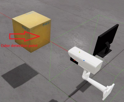
3. Camera Remote
Is used to place a camera with monitor to view strategical places to be monitored by operators.
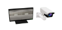
The remote camera has also the following functions:
- Detect movement using the PLC Input:
PLC_IN_MOVEMENT. When this PLC Input is configured, the camara will activate this PLC Input when movement will be detected in the central area of the Camera focus.
- Detect the WorkParts colours, returning the red, green and blue colour components assigned to three analog PLC inputs. The captured point is at the center point of the camera.
Using the Script or Graphic code function TakeSnapshot(string path) the camera will save in the passed path, a png file with format dd_MM_yy HH_mm_ss.png with the camera capture image.
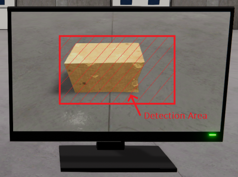
4. Vision Sensor
This special vision sensor is used to detect WorkParts in the sensor’s scanning area and provides information about:
- The spatial (X,Y,Z) coordinates these detected WorkParts are in space relative to the camera position.
- The rotation of the scanned WorkParts, the rotation is relative to the word position, not to the camera.
- The WorkPart type for the detected ones.
- The size of the scanned WorkParts (X: width, Y: height, z: length).
This sensor is capable of detecting all the WorkParts that are within the vision area. The sensor can be used to give the WorkPart positions to Robots, Gantry’s, Axis, … and be able to pick them up or handle them at your convenience, or measure the WorkParts dimensions (X: width, Y: height, Z: length). Use the PLC Output PLC_OUT_MODE to change between the coordinate or measure modes, if PLC_OUT_MODE is false the sensor will provide the coordinates, if is true the dimensions.