Transports
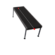
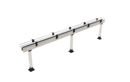
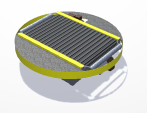
1. Conveyor Belt 1
It is used to transport WorkParts. Is possible to configure it to work in digital or analog mode.
- In digital mode uses two PLC outputs (
PLC_OUT_ADVANCEandPLC_OUT_REVERSE) to activate the conveyor in both directions. - In analog mode uses one analog PLC output (
PLC_AOUT_SPEED) to set the belt speed, if speed = 0 belt is stopped, if speed > 0 belt moves forward, if speed < 0 belt moves backward.
Is also possible to use an incremental quadrature encoder to control the belt position by the PLC.
To do it are used two digital PLC inputs: Encoder_PHA and Encoder_PHB. When these two outputs are used, the conveyor reductor shows the encoder:
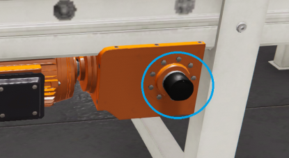
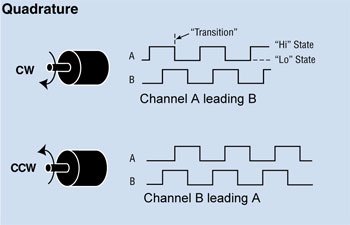
How the quadrature encoder works? The code disk inside a quadrature encoder contains two tracks usually denoted Channel A and Channel B. These tracks or channels are coded ninety electrical degrees out of phase, as indicated in the image below, and this is the key design element that will provide the quadrature encoder its functionality. To know where direction sensing is required, a controller can determine direction of movement based on the phase relationship between Channels A and B. As illustrated in the example optical encoder figure below, when the encoder is rotating in a clockwise direction its signal will show Channel A leading Channel B, and the reverse will happen when the quadrature encoder rotates counterclockwise.
PhysicMode: if this property is set to true the WorkParts on the conveyor belt will be moved using physics forces, more realistic that default mode, but more expensive at resource computer level. Use it when you need to transport WorkParts between different conveyor belts.
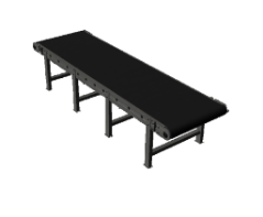
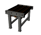
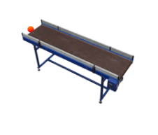
2. Conveyor Belt 2
It is used to transport WorkParts, uses one PLC output to active the conveyor.
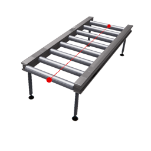
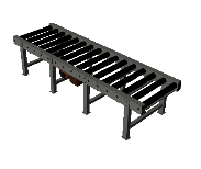
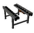
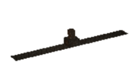
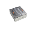
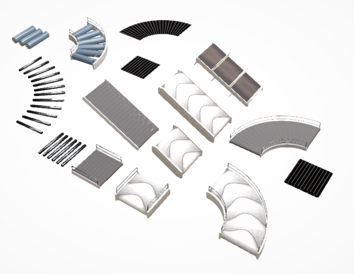
3. Conveyor Roller 1 & 2 (small/medium/large)
It is used to transport WorkParts, uses two PLC output to move the conveyor in two different senses.
4. Conveyor Belt Transfer
Used to pass WorkParts form one conveyor to other in 90 degrees, uses two PLC outputs to active the conveyor in both directions.
5. Conveyor Chain
Used to move Parts in two senses, useful to transfer WorkParts between two roller conveyors located at 90 degrees. Uses the following PLC signals:
- PLC Outputs:
- Advance: advance rollers, moves WorkParts forward
- Reverse: reverse rollers, moves WorkParts backward
- Rise: if true moves chains up, if false move chains down.
- Chain Right: if true starts the movement chains to right to move the WorkParts to the right
- Chain Left: if true starts the movement chains to left to move the WorkParts to the left
- PLC Inputs:
- Chain Up: true if the chains are in upper position, false if are in lower position.
6. Free Conveyor
Conveyor roller used to load/unload parts in the Stacker machine, uses two PLC outputs to active the rollers in both directions.
7. Conveyor Stop, Roller & Belt
Used to stop WorkParts moved by the different types of conveyors, uses one PLC output.
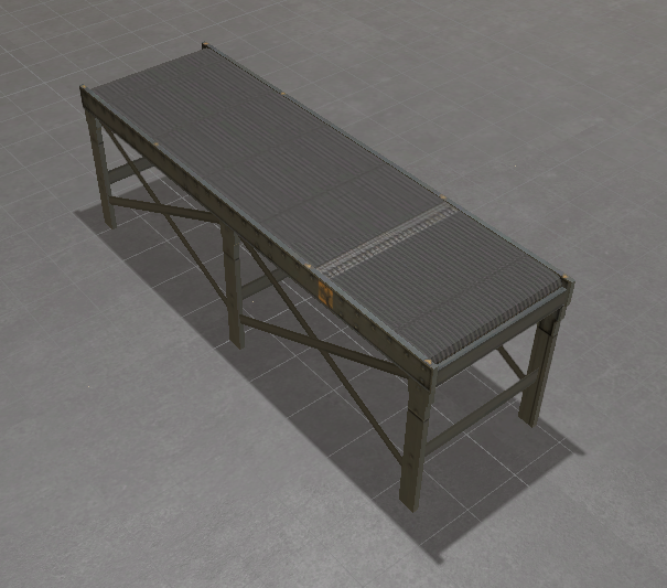
8. Conveyor Simple
It is used to transport WorkParts, uses two PLC output to move the conveyor belt in two different senses.
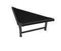
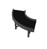
9. Curved Belt
Belt for curves, uses one PLC output to activate the conveyor.
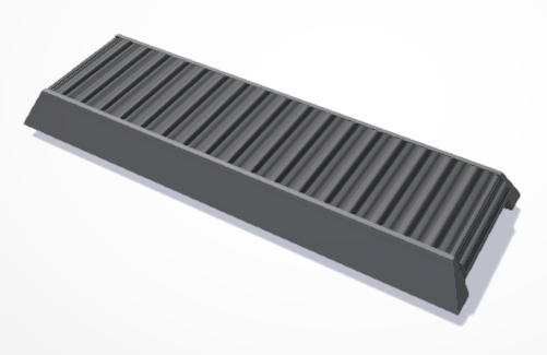
10. Thin Conveyor
Conveyor for transport small parts, like bottles, cans or similar. The guides can be customized to adjust to parts, like separation, length or input/output angles.
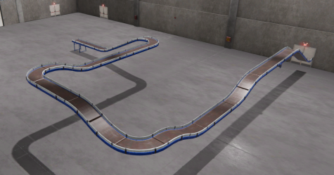
11. Conveyor Builder
This component allows to create complex conveyor layouts in an automated and very simple way using different conveyor parts. Once placed, click on the red dot to create the next conveyor section.
PhysicMode: if this property is set to true the WorkParts on the conveyor belt will be moved using physics forces, more realistic that default mode, but more expensive at resource computer level. Use it when you need to transport WorkParts between different conveyor belts.
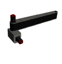
12. Selection Arm
This device moves 90 degrees to left or right with the objective to distribute WorkParts on the conveyor belts, uses two PLC outputs, one to move left and other to move right.
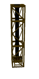
13. Elevator
Used to lift and move WorkParts, uses two PLC inputs and six PLC outputs.
14. Elevator Big
Used to lift & move WorkParts, uses the following signals:
- PLC Digital Outputs:
PLC_OUT_GO_UP: moves the elevator to upper position, stops when the signal is false.PLC_OUT_GO_DOWN: moves the elevator to lower position, stops when the signal is false.PLC_OUT_ADVANCE: moves roller in advance directionPLC_OUT_REVERSE: moves roller in reverse direction
- PLC Digital Inputs:
PLC_IN_SW1: active when photocell 1 is active (input position)PLC_IN_SW2: active when photocell 2 is active (output position)
- PLC Analogic I/O:
PLC_AOUT_ELEVPOSITION: moves elevator to the value indicated by PLC analogic outputPLC_AINP_ELEVPOSITION: current position of elevator written in PLC analogic input
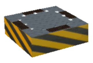
15. Join Table
Used to move WorkParts in two senses, uses eight PLC outputs to move the stops and the rollers.
16. Sorter Table
Use it to send WorkParts to different angle positions.
PLC Outputs Signals:
- RUN: activates the rollers to move parts.
- RIGHT60: moves rolls 60 degrees to right
- RIGHT90: moves rolls 90 degrees to right
- LEFT60: moves rolls 60 degrees to left
- LEFT90: moves rolls 90 degrees to left
- RESET POSITION: moves rolls 0 to home position
- PLC_ANALOGIC_OUT_ROT: rotates the rollers the plc analogic value.
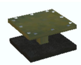
17. Turn Table 1
Used to move WorkParts with micrometric precision, uses two PLC inputs and four PLC outputs.
18. Turn Table 2
Used to move WorkParts to different angle positions, uses the following PLC signals:
- Digital Outputs: * Advance: move rollers in advance direction
- Reverse: move rollers in reverse direction
- Rotate: rotates the table 90 degrees
- Clockwise: if true the rotation is made in clockwise, if false counter clockwise
- Stop: stops table rotation.
- Home: Moves the table to home position.
- Digital Inputs:
- Stopped: true if table is stopped.
- Moving: true while the table is turning.
19. Conveyor
Different predefined tray conveyors (with or without opening/close door).
20. Metal Conveyor Belt
A metal tray conveyor belt.
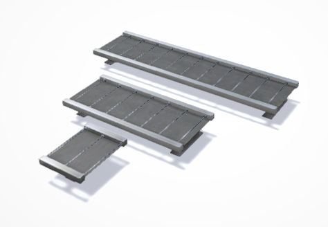
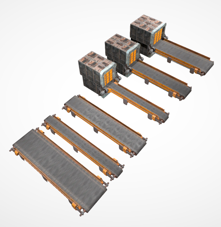
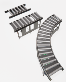
21. Modular Conveyors
Here are available different types of conveyors sections, in order you can customize the conveyor layout.
22. Small Conveyor Roller
Other type for conveyor roller, used to transport WorkParts, uses two PLC output to move the conveyor in two different senses. There are three types: Large, Small and curve.
23. Conveyor Procedural & Conveyor Roller Procedural
It allows to procedurally create a belt or roller conveyor system where you can configure the length, width, and height of the conveyors, allowing you to create curves and any type of layout.