Basic Shapes
With your Machines Editor program are packed a set of components ready to use. Some of them are very specific and others are more general and can be used for many uses due are very customizable.
Following a description of each one of the components is explained, and the more general components are explained more detailed.
1. Static Element
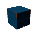
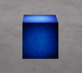
Is an element not affected by gravity or by the action of external forces, always is collisionable with other components. Can be joined with dynamic elements. Use this component to set any object that will be static and needs not be affected by gravity. By default is shown as a blue box, but changing their properties, you can customize it.
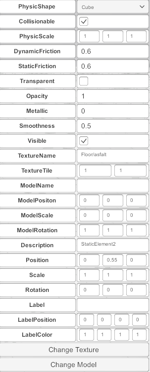
Here are listed all of their properties:
- PhysicShape: the shape of the component, can be cube, cylinder, sphere or capsule.
- Collisionable: is true the components have a collisionable body.
- Physic Scale: the scale of the Physic shape.
- Dynamic Friction: The friction used when already moving. Usually, a value from 0 to 1. A value of zero feels like ice, a value of 1 will make it come to rest very quickly unless a lot of force or gravity pushes the object.
- Static Friction: The friction used when an object is laying still on a surface. Usually, a value from 0 to 1. A value of zero feels like ice, a value of 1 will make it very hard to get the object moving.
- Transparent: activates the alpha channel for this component and can show a transparent effect (like glass).
- Opacity: alpha channel value for transparency.
- Metallic: metallic effect (0 to 1)
- Smoothness: smooth effect (0 to 1)
- Visible: if true does not view in run mode.
- Texture Name: the texture to apply to the component (Use change Texture button to change it).
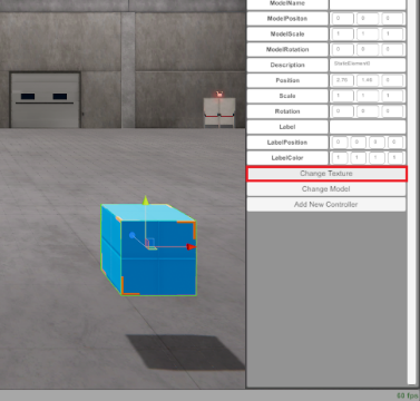
Press Change Texture from Property grid, to view the texture Selector Window.
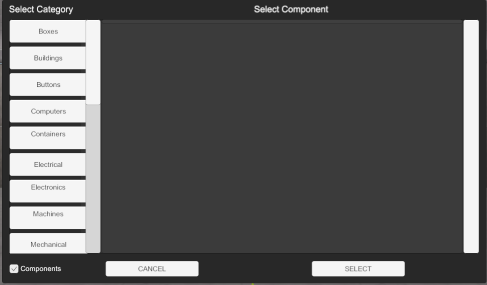
Then the Texture preview Window will appear in order to select the texture to be applied to the component:
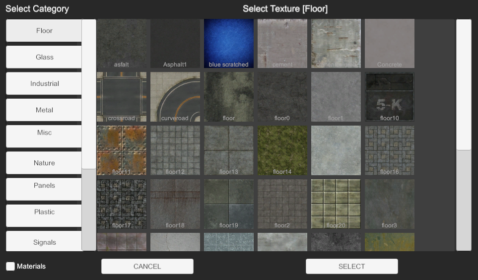
Navigate in the window to select the desired Texture, Press Left Category buttons to change Texture types.
Once you have chosen the desired texture, press Select button, then the texture will be applied to the component:
Instead of assign a texture, you can assign a Material to the component, the materials have more rich information about how the light will interact with the environment, and the graphic effect have more quality. To select a Material, click in the Texture preview window, the check box Materials located in the bottom of the Categories, then all the available Materials will be shown, click in the desired to apply it to the component:
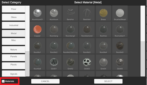
Is possible to assign a Material in the Texture preview Windows, clicking in the Materials check box.
The selection Texture window is available to all components that have a texture property! (like dynamic element, Plane, WorkParts, …) by the button Change Texture in the property grid.
- Texture Tile: the texture repetition over the component.
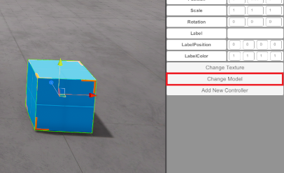
- Model Name: the Model or Component assigned to the Static Element. Is used change the visual shape and customizing the appearance. To show the model selector window press Change Model button in the property grid when the component will be selected, once pressed, the model selector window will appear and here you can select from the list the desired model to be assigned to the component. Press from left button categories list, in order to navigate for all the model’s library. Press select to choose the desired model.
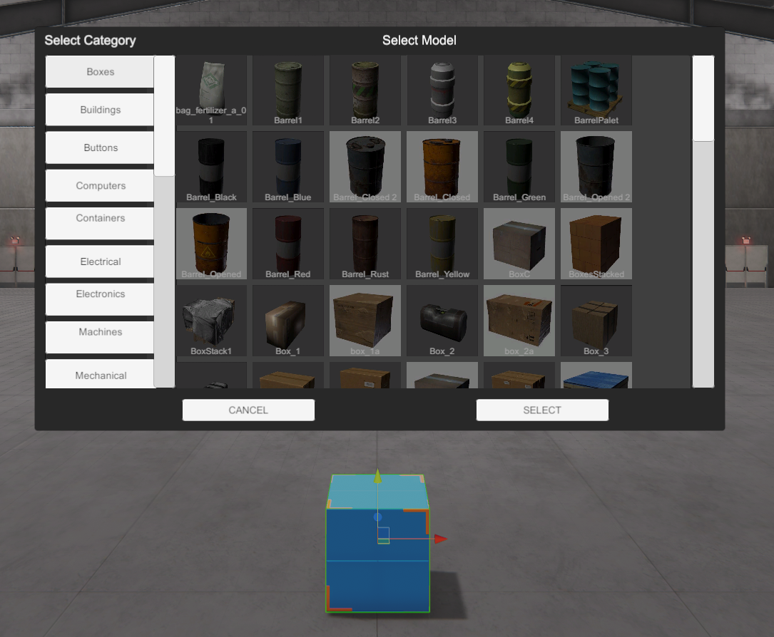
If instead a model you want to assign a Component, press the checkbox Components located in the lower left:
- The model is a non collisionable object that remains inside the Static Element, the model has not collision or physic behavior, the model must to be fitted inside the static element shape.
- The Component is an object that has collision shape and physics, when a component is selected, the static element will have the shape and collision of the selected component.
- Model Position: sets the model position inside the component (not valid for Components, only valid for Models).
- Model Scale: sets the model scale inside the component (not valid for Components, only valid for Models).
- Model Rotation: sets the model rotation inside the component (not valid for Components, only valid for Models).
- Description: how this component will be named in this machine. IMPORTANT: This name will be the reference in the script code. Each machine component must to be a description and cannot be repeated.
- Position / Scale / Rotation: the space properties of the component.
- Label / Label Position / Label Color: the text label and parameters assigned to the component.
Using controllers (see Controllers section), it is possible to customize the behavior of the component to make it move or rotate depending on the necessary conditions.
2. Dynamic Element
Is a component that is affected by the gravity, can be moved by others elements or forces and can be joined to others dynamic elements or static elements. By default, when is added to the machine, is presented as red small box, but changing their properties you can customize according your needs.

Dynamic Element have some special properties and others are equal to Static element. Here are described the special properties:
- Bounciness: How bouncy is the surface? A value of 0 will not bounce. A value of 1 will bounce without any loss of energy.
- AirResisstance: how much air resistance affects the object when moving from forces. 0 means no air resistance, and infinity makes the object stop moving immediately.
- AngularAirResistance: how much air resistance affects the object when rotating from torque. 0 means no air resistance.
- Mass: The mass of the object (in kilograms by default).
- Fix To Element: here is set the id number or description name of the Static Element, Dynamic Element or Plane Element this component is attached to.
- Constraint Position: here are configured the 3 axes where the movement is constricted in order this component have a special behavior. Set 1 to restrict movement on an axis, a 0 allows the movement. For example (0, 1, 0) restricts the gravity movement of the component, the dynamic element will move left, right, forward and backward but not up and down.
- Constraint Rotation: here are configured the 3 axes where the rotation is constricted. Set 1 to restrict rotation on an axis, a 0 allows the rotation.
3. Plane Element
A plane that could be used for multiple uses, could be collisionable or not, you can change their texture to customize to your needs. Also, could have a customizable texture that could be moved by a PLC input/output. Useful to make belts, or moving elements.
This component has some special properties, here are described:
- PLC_OUT_ADVANCED: if enabled (value > -1) the texture will move forwards if this plc output is on.
- PLC_OUT_REVERSE: if enabled (value > -1) the texture will move backwards if this plc output is on.
- Speed: the speed of the texture when moving.
- Offset Speed: the speed of the elements on the plane when moving.
- IsFloorVR: only used for Machines Simulator VR, if is true, the user can tele transport to this component (useful to make platforms, ladders, etc.)
- ChangePartRotation: when a WorkPart is on the plane, if this property is set to true, the WorkPart will rotate facing the forward direction of the plane.
- PhysicModePush: if this property is set to true the WorkParts on the plane will be moved using physics forces, more realistic that default mode, but more expensive at resource computer level.
4. 3DModel
This element is a 3D shape with or without collision or physics behavior. Use the Change Model property to assign a customized 3D model from library. Also, could be linked to any component using their property FixToElemName.
Set the property IsStatic to true if the component will not be moved or called by any function during the simulation execution (normally for decoration elements). This will improve performance in simulation.
Set the Property Collisionable to true if you want to use the 3DModel shape as a collision shape. You can also set the material properties for friction.
- Performance: It is highly recommended to use low-poly models for this mode, otherwise the computer can slow down with models with a lot of geometry.
- Movement: In this mode, the 3Dmodel must always be set in the same position. Do not use moving functions to change their position or parent it with moving components.
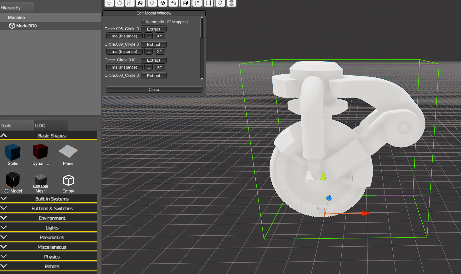
The 3Dmodel component includes a special feature to work with imported models and be able to texture them and/or break them down into the desired parts. Press the Edit Model button (located in the property panel) to open the model editor window:
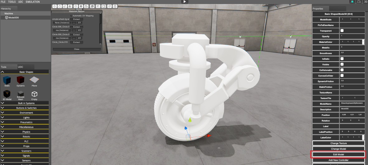
From the Edit model window, you have available the following functions:
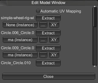
- Automatic UV Mapping: if the imported model has not information about UV mapping, select this option and Machines Simulator will try to map automatically the model to the textures.
- Press Extract button to extract the mesh part of the model, creating a new Model3D component with this mesh assigned.
- Press on the Material name assigned to the mesh to identify it.
- Press the three dots button to select the texture or material to apply to the mesh.
- Press the XY buton to apply a Texture Tile on the mesh.
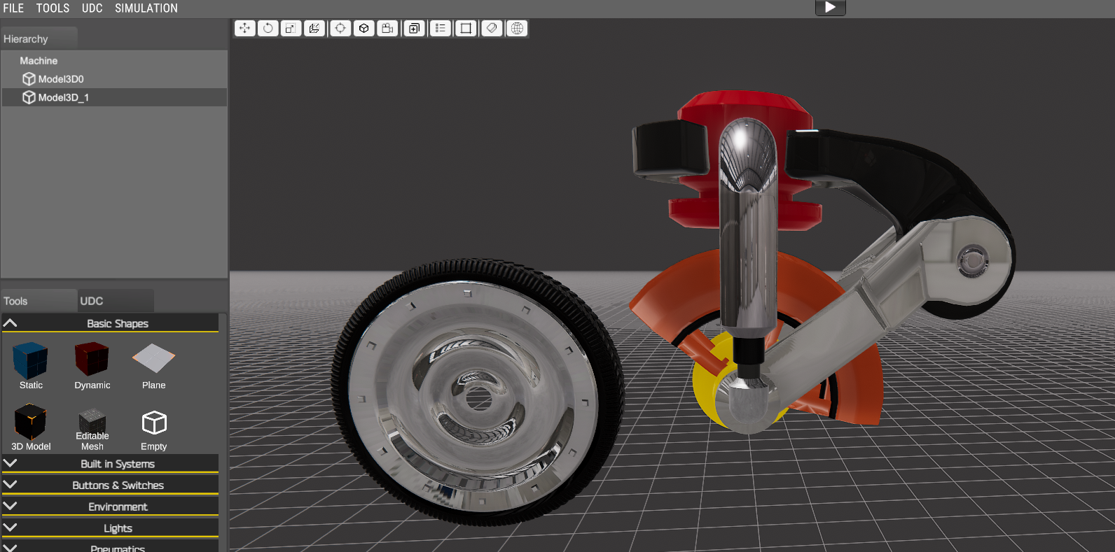
Example: Using the Edit Model feature of Model3d we can conver this imported obj model.
into a model3D structure:
5. Editable Mesh
This is a special component designed to create your own 3d Models with the included mesh editor.
Press Edit Mesh in the property grid to start the mesh editor:
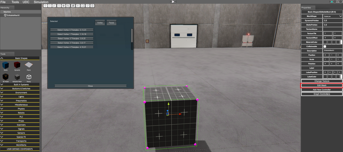
Two edit modes are available, Vertex edit mode and Face edit mode.
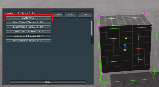
Vertex Edit mode: Click on each mesh vertex (mark in magenta color) and move it using the position or scale Gizmos. Click Left Control Key to select a group of vertices. In order to select a group of vertices, click left Shift key and press left mouse button, then select all the desired vertices with the selection rectangle:

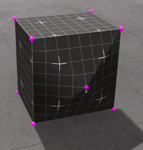
Selecting two vertices is possible to create a new vertex in the middle position of both:
For each vertex is possible to change the UV map selecting from the vertex slider the desired position. Use the Undo button to go back if the results are not as desired.
Face Edit mode: If face edit mode is selected we can edit the mesh working in their faces, the following operations are available:
- Move Faces: place mouse over the desired face and drag mouse to move the face.
- Extrude Face: press left control key and place the mouse over the face to extrude.
- Bevel Face: press left control key and place the mouse over the face to create a bevel.
- Detach Face: press left control key and place the mouse over the face to detach.
- Delete Face: press left control key and place the mouse over the face to delete.
- Subdivide Face: press left control key and place the mouse over the face to subdivide right in the middle of its vertices. Useful if you need to create more geometry.
- Merge Face: press control key and press left mouse click on each face to merge.
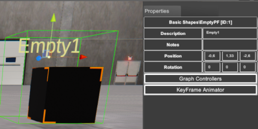
6. Empty
Use this component to group components over the same parent and/or make keyframe animations. Grouping components will allow to organize components when using a big amount of it.
Empty component has an important feature called KeyFrame Animator. Using this tool is possible to make easy or complex animations without program any line of code, use controllers or graph code.
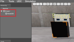
How to use the KeyFrame Animator Tool Add a new Empty component to your simulation, add a new Model 3D component and parent it with the Empty component:
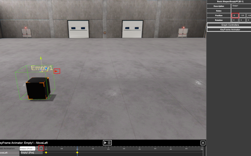
Select the Empty component, in the right property panel, click the button KeyFrame Animator:
The KeyFrame Animator tool will appear in the bottom side of the screen, you can move it or resize using the right bottom resize control:
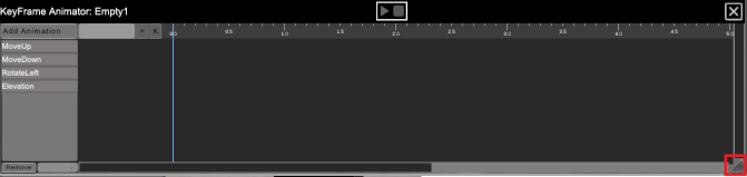
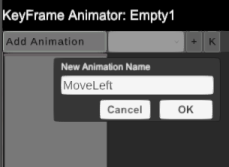
Once the Empty component is selected (if not, the KeyFrame Animator will be disabled) click on the Add Animation button to create a new animation. On the New Animation window type a name and click OK:
From the animator drop down properties’ component list, select the component you want to animate (the drop down component list will be filled with all components the Empty component will have as children’s), in this case:
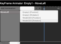
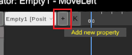
You can choose from each component two properties to animate the position or the rotation, select in this case the Empty1 Position and click on the Add new property button to add it to the time line:
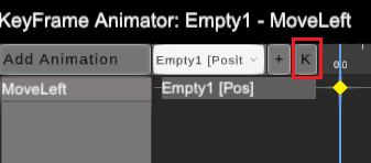
Now select the start position for the animation and click in the Add new KeyFrame button:
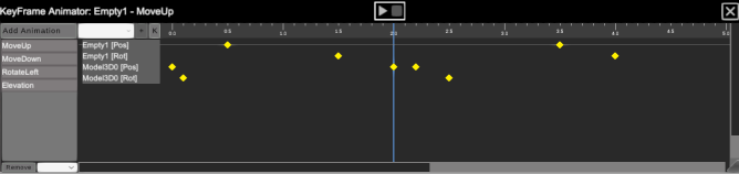
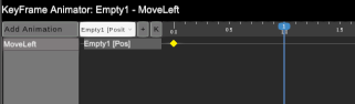
A yellow diamond will be added to the time line where is saved the position (in this case) or rotation assigned, to this animation time line tenth of a second.
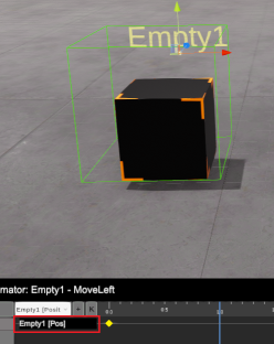
Now place the mouse over the blue time line cursor and move it pressing the left mouse button to the destination time position for the new keyframe value (1 second in this case):
If you make mouse left click over the component property added in time line, this will be selected on the Editor, making easier to move or rotate it to save their value:
Move the component to the left 5 units (meters) moving the red gizmo arrow or typing the X position value in the right Property panel, the make click on the Add new keyframe button:
A new keyframe is saved. If you move the time line cursor you can view each saved position for each keyframe, the selected component will be placed & rotated in the keyframe value selected.
Now select from the drop down list the Model3D rotation property and add it to the animation, set the keyframe cursor on 0.0 seconds, selecting the Model3D0[rot] button, and press Add keyframe button. Now set the keyframe cursor on 0.5 seconds, change the rotation on Y axis to 90 and press Add keyframe button.
Press Play Button to see the animation, the empty component will move from 0 to 5 and the model will rotate 90 degrees from 0 to 0.5 seconds. You can update each keyframe value if you place the time line cursor over it and press again the add keyframe button with the new value. Remember to have selected the proper component property line to update their value.
Also is possible to update each keyframe value if their horizontal line is selected (their assigned component is selected) and make mouse right click over it, you will see the keyframe properties and values on the upper side of the Animator window:
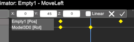
There you can change their value for each axis, you can delete it if you click on the cross icon or confirm it pressing the check icon.
By default acceleration are applied for all the animations, the movement or rotation starts, is accelerated until arrives to the middle position (or rotation) then deaccelerates again until the final destination. If you need the animation will run linear then select any of the keyframes for the animation line property and set the Linear check in their property, this will affect to all the keyframes for this line.
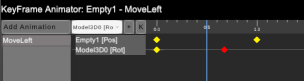
You can move a Keyframe value clicking over it with left mouse and moving it in the time line:
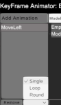
Each animation has three play modes, Single, Loop and Round:
- Single: the animation is played once and stops when is finish.
- Loop: the animation is played looped.
- Round: the animation is played in loop mode but at the end it goes back and then starts again.
To change the animation mode, select the desired animation and change the mode in the bottom drop list:
Press Remove animation button to remove the selected animation.
The Time Line animator has a limit of 10 seconds, but changing the animation speed you can create larger animations, for instance if you configure an animation of 10 seconds, but the playback speed is set to 0.1 seconds, it will take 100 secs. The KeyFrame Animator allows to play with Position, Rotation and Scale. The Scale only is available for the Static components and Model3D component which are children of the Empty element that has the KeyFrame controller.
How to play animations
In order to execute the animations, use the script code or the Graph code. For the previous example, if you want to play the animation when PLC output 0 is on, write the following script code:
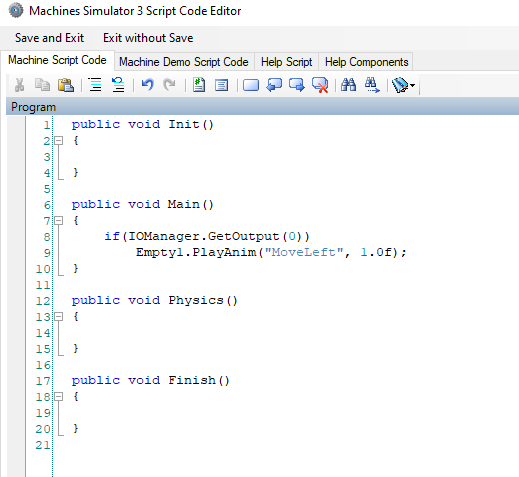
Or in the Graph Controllers:
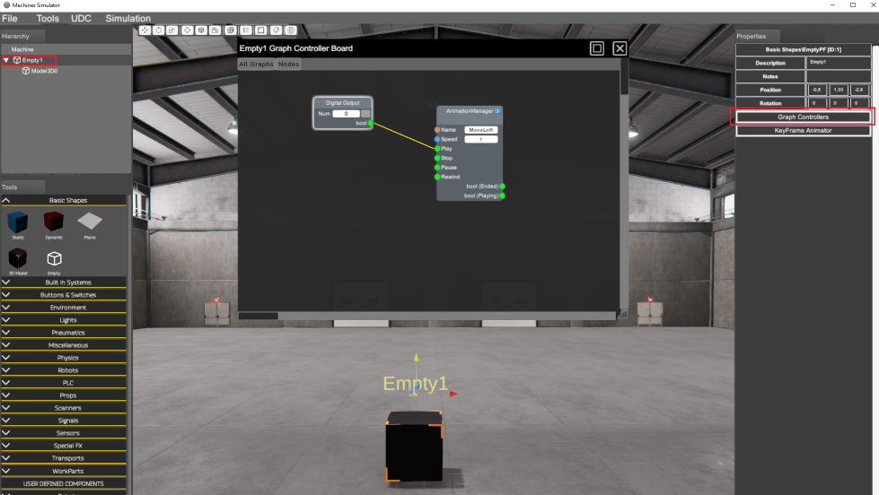
The Animation Manager node has the following nodes:
Input Nodes:
- Name: the name of the animation to play
- Speed: the animation speed.
- Play: if true the animation is played
- Stop: if true the animation is stopped
- Pause: if true the animation is paused
- Rewind: if true the animation is played in rewind mode (end to start)
Output Nodes:
- Ended: true when the animation is finished
- Playing: true while the animation is being played.