Robots
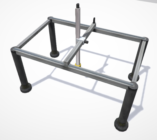
1. Axis Gantry
It is used to transport WorkParts with micrometric precision, uses three analogic PLC inputs and three analogic outputs to set axis coordinates, one PLC digital output to activate magnet and take WorkParts, and one digital input to inform that a WorkParts is taken. Use the Test Mode property to move axis with numeric keys (1 to 9) to move axis and make tests.
2. Small Gantry
Same as previous component by used for smallest proposes. Also incorporates a one more axis that allow to rotate the parts take with the suction system.
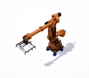
3. Solder Robot
Robot with solder sparks effect to simulate soldering. Uses PLC analogic I/O to manage axis. Use the analogic PLC outputs to drive the robot axis, the PLC analogic inputs are used to read the current axis positions. Use the Test Mode property to move axis with numeric keys (1 to 9) to move robot axis and make tests.
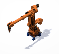
4. Picker Robot
It is used to move WorkParts with micrometric precision uses PLC analogic I/O to set axis coordinates, one PLC input and one PLC output to take parts. The speed and detection distance can be customizable. Use the analogic PLC outputs to drive the robot axis, the PLC analogic inputs are used to read the current axis positions. Use the Test Mode property to move axis with numeric keys (1 to 9) to move robot axis and make tests.
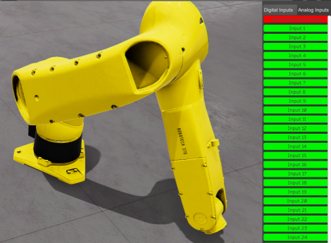
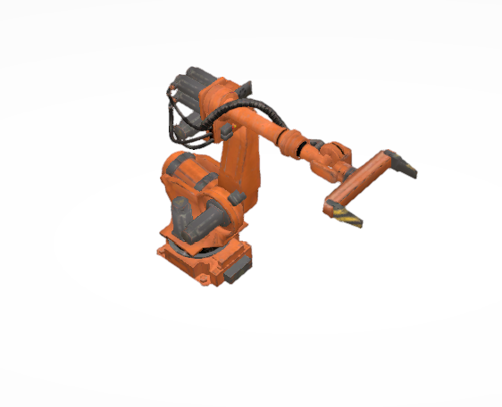
5. Robot Articulated
This is a special Robot that can be used for your own proposes. By default, you can configure three different kinds of grippers (gripper for big or small parts or suction system), but you can assign any component available in the machine to be use as tool, to do it, select the GripperType property to ‘None’ and assign in the ToolComponent property the id of the component you want to link in the tool of the robot. Use the analogic PLC outputs to drive the robot axis and velocity, the PLC analogic inputs are used to read the current axis positions. Use the Test Mode property to move axis with numeric keys (1 to 9) to move robot axis and make tests.
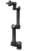
6. Cobot type 1
Collaborative Robot with 6 axes. Uses one Vacuum system to catch parts. Due to their level of security and low speed, these robots can work in collaboration with human operators and do not require fencing.

7. Cobot type 2
Collaborative Robot with 6 axes. Uses one Vacuum system to catch parts. Due to their level of security and low speed, these robots can work in collaboration with human operators and do not require fencing.
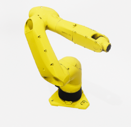
8. Industrial Robot
As the Articulated Robot, this is a general-purpose robot with 6 axes. Uses one digital PLC output to take parts, and one digital PLC input to inform about when detects a part to take. Using the ToolComponent property can be linked to any of the machine components to use it as the tool for the robot. The size of the grip system and the distance from the last axis can be configured with the GripScale and GripOffset properties, in order the grip system would be able to detect parts, must not be in contact with any component (customized tool).
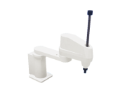
9. Scara Robot
SCARA type robot with four degrees of freedom with horizontal positioning. Uses one digital PLC output to take parts, and one digital PLC input to inform about when detects a part to take. Using the ToolComponent property can be linked to any of the machine components to use it as the tool for the robot, by default a sucker device is present as robot tool but can be hidden in the case a customized tool will be used. The size of the grip system and the distance from the last axis can be configured with the GripScale and GripOffset properties, in order the grip system would be able to detect parts, must not be in contact with any component (customized tool).
This robot can be managed by the PLC in normal mode, moving each of the 4 axes independently, or can be manager in in trajectory mode (Inverse Kinematics mode) indicanting a 2D coordinate in space (X and Z) and the two first axes will move to this position. The vertical axis and the rotation axis are not included in the IK movement. If you choose the IK Mode (activating the PLC Output PLC_OUT_IKMode), the analog PLC outputs PLC_AOUT_ARM1AXIS and PLC_AOUT_ARM2AXIS will set the coordínate for X and Z position respectively.
Robot Management
The Robots can be managed in several ways:
- Directly by the PLC for each axis using the analog I/O for position and speed.
- Using the Script Code or Controllers to set the position routes.
The first one is less realistic, but is possible to take the total control of the Robot axes (not used in real life), the second one allows to configure manually the robot routes for each task (take parts, make movements, etc…) and later using PLC I/O to give the orders to start the robot’s routes.
For the first method, configure the PLC analog I/O for each axis of the robot (also is possible to configure PLC analog outputs to set the axis speed), then assign the desired values to the PLC analog outputs to move the robot axis, reading the PLC analog inputs are know the axis current positions.
To know where positions the Robot must to go, use the Test Property (only available in the editor mode).
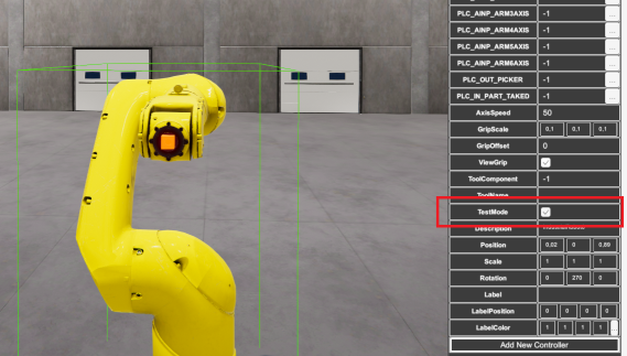
Setting Robot in Test Mode
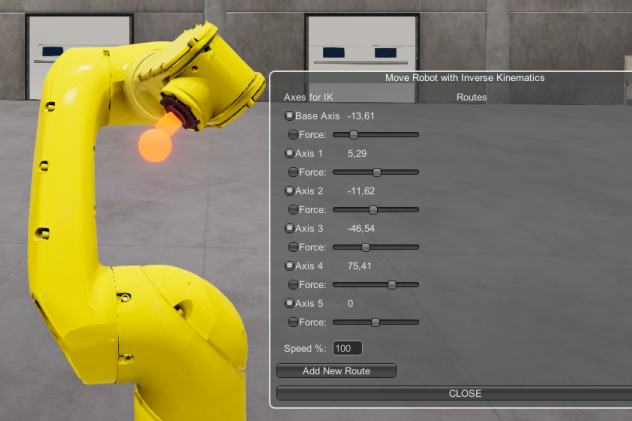
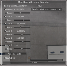
When the Machine is in Run Mode, the Move Robot with Inverse Kinematic control panel will appear, mark all the Axes check boxes Force in order you can use can use the number keys (1,2,3,4,5,6,7,8 and 9) to move the Robot Axes:
Use the keys:
- 1 and 2 to move the Axis 1
- 3 and 4 to move the Axis 2
- 5 and 6 to move the Axis 3
- 7 and 8 to move the Axis 4
- 9 and 0 to move the Axis 5
- O and P to move the Axis 6
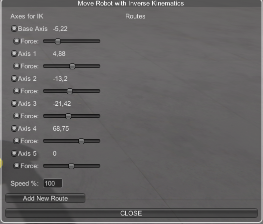
In this window are shown the axes values, use it to know the Robot axes values to set the positions with the PLC.
Setting Robot in Test Mode in Inverse Kinematics mode
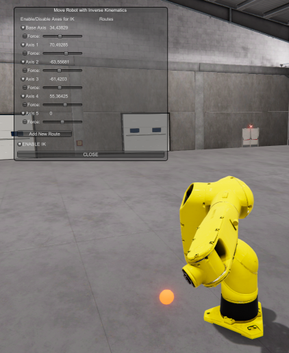
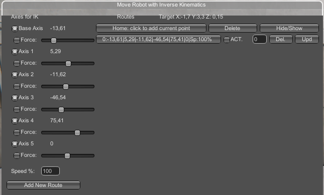
For the second method, you must to use Inverse Kinematic Robot feature, if the Test Mode property is true, when starts the simulation, the Robot will move in Inverse Kinematics mode, this means that you can move the robot with the mouse to place it in the desired position.
To allow the Robot will move in Inverse kinematics mode, be sure all the check boxes Force for all axes are disabled:
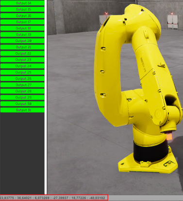
When the Inverse Kinematic mode is active, a red sphere will be placed in the last axis of the Robot, place the mouse cursor over the sphere and click left mouse button to move the robot to the desired positions:
Also, you can use the sliders from the control panel to move each robot axis, click the Force check box to allow the manual slider movement, also if is needed to control a particular axis in a special position. When is needed a lot of precision, you can force the axes and move slowly using the keys mentioned above.
Creating Robot Routes
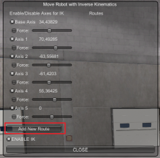
A Robot route can be formed by a certain position of the robot axes or by multiple of them. To create one route, follow the following procedure:
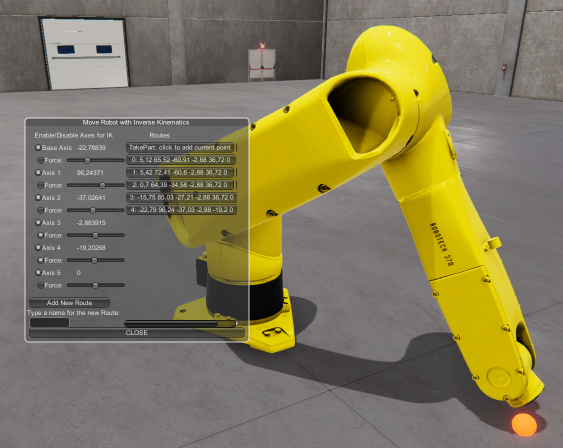
- Press from the Move Robot with Inverse Kinematic floating control panel the button Add New Route:
- Type a name for the route and press the Add button:
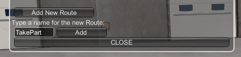
- Then a new Button will appear in the Routes Section:
- Now place the Robot axes in the desired position for this route and press the Route Button to save it in this Route:
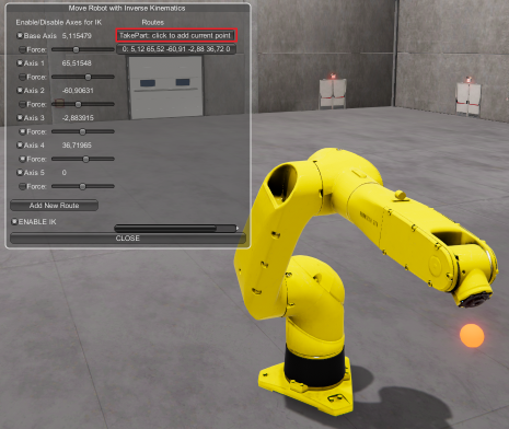
- The axes position will be saved, click over the Route button for all the position you want to save for this route:
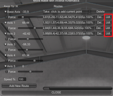
In this example, the route named TakePart is composed by 5 axis positions (called points). When this Route will be called, the robot will follow sequentially all the points routes starting from 0 to the last number available.
You can click in each point button, to move the Robot to the point position in order to check the axis positions for each take point. Is possible to delete a Route or point in the route clicking the right ‘Del’ button:
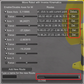
If you want to change an existing point, move the robot to the desired new position and press the Update (‘Udt’) button for this point:
Each route point has the following fields:
- The angular values for each robot axis.
- The % speed the robot must to reach this position.
- ACT field: If true the PLC digital output that is assigned to the robot tool will be set with this value. Useful to activate suctions devices of grippers when the robot is in this route position.
- Delay Value (In seconds): the time (in seconds) the robot must wait when reaches this point route.
The Hide/Show button for each route allows to show/hide the list of all points that compose the route.
How to call the Routes in Run mode:
The routes can be called by scrip code or by Controllers.
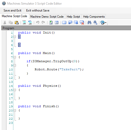
Scrip code example: Use the Route Robot method:
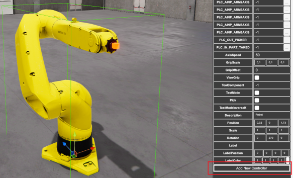
Controller example: Select the Robot in the editor and click over the right property grid ‘Add New Controller’ Button:
Now click on the Controller_1 created button and configure it as follows:
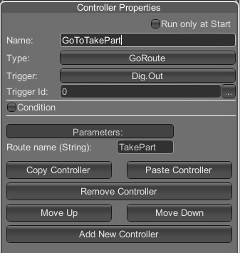
- Name: GoToTakePart (or whatever descriptive for this action)
- Type: Select form the list
GoRoute - As Triger select Digital Output (
Dig.Out) - As Trigger Id, type the PLC output number used to move the robot to Route TakePart (
0in this example). - Parameters:
- RouteName: type
TakePart(the route name we have configured before). Instead type the name, you can click the Select Route button to select form the list all the available Routes:
- RouteName: type
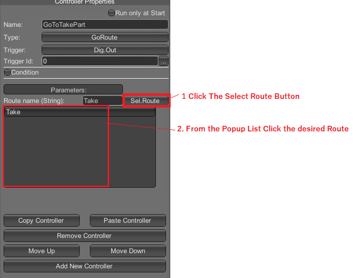
Now when the PLC will active the PLC output 0, the Robot will move sequentially for all the points that make up the route TakePart.
If you want to know when the Robot has stopped, add a new controller and use the following configuration:
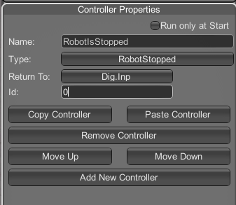
When the Robot will finish the Route, will activate the PLC Digital Input 0: