User Defined Components (UDC)
The UserDefinedComponents are special components created with other components (all described above). These components can be added to the Machines Simulator, copying the .udc files to the folder UserDefinedComponents.
Properties:
- Position, Scale & Rotation: Space 3D properties to place, scale and rotate the component.
- Label, LabelPosition & LabelColor: assigns a description label with position and color.
- Edit Digital Inputs: when pressed appears a new window where can be set the address of the Digital inputs assigned to this UDC.
- Edit Digital Outputs: when pressed appears a new window where can be set the address of the Digital outputs assigned to this UDC.
- Edit Analogic Inputs: when pressed appears a new window where can be set the address of the Analogic inputs assigned to this UDC.
- Edit Analogic Outputs: when pressed appears a new window where can be set the address of the Analogic outputs assigned to this UDC.
- Edit Parameters: when pressed appears a new window where can be set the numeric values (float) of the parameters assigned to this UDC.
- Edit Parameters List: when pressed appears a new window where can be choose the desired parameter from the available on the list.
UDC Editor Mode
It’s very difficult to provide all the machines, components, systems, devices needed to cover the entire user requirements, for example in each type of industry are used different types of components, we would need thousands of components to be able to create all the possible installations.
The solution is the Components Editor, where the users can create their own components and give the desired behavior to interact with the installation. These are the User Defined Components.
All the created components can be shared with all the users. Visit often the www.nirtec.com web site to download new components.
All the components seen until now are system components and are customizable via properties, but the User Defined Components (UDC in advance) are a step more, you can change all of them, shapes, models, textures and behavior. Once created and saved, the UDC are located in the UserDefinedComponents folder of your application path, and resides in an individual file with extension .udc.
These files can be shared and automatically are loaded at the start of Machines Simulator to be ready for your machines.
UDC Editor Interface
To enter in the UDC Editor, select form UDC menu bar the Create New UserDefinedComponent menu item, then a new panel will be located at the left side, here you will see a tree with the component hierarchy:
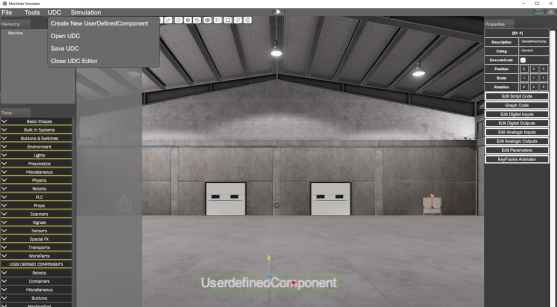
- Create New User Defined Component: Creates a new UDC Component.
- Open UDC: Opens a new UDC component.
- Save UDC: Saves the current UDC component.
- Close UDC Editor: Closes the UDC Editor.
The UDC Editor works in the same environment your machine is, then you can create the UDC according the same scale the current machine.
The User Defined Components are a set of one or more components from the Component tree, each one could have their own properties and can have a special behavior. The User Defined Component is a group of components related to each other and that will have a common goal, and can have a script code associated in order to have a special behavior or not.
UDC Main Object Properties
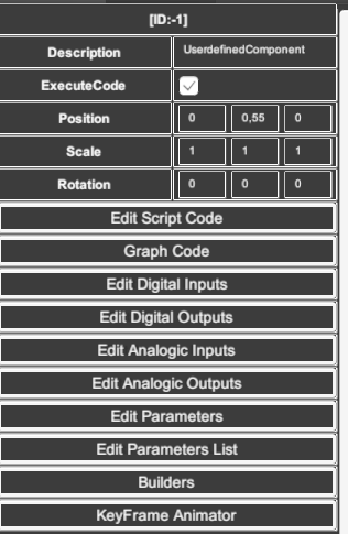
Selecting the UDC main object (the main parent, is the first item in the UDC hierarchy tree) their properties are shown in the grid located at the right side.
UDC Property List:
- Description: the name of the UDC
- Execute code: if true the UDC will have a special behavior and will have assigned a script code to customize how it works.
- Position, Scale & Rotation: the 3D space properties to place, scale and rotate the UDC.
- Edit Script Code button: when pressed, the script editor is opened and here we can program the UDC behavior.
- Graph Code button: starts the graph code editor to program the UDC behavior using the graph nodes language.
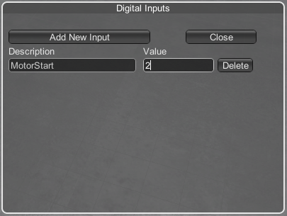
- Edit Digital Inputs: when pressed appears a new window where we can add the Digital inputs assigned to this UDC. Press Add New Input button to add new inputs, also you must to enter the address this UDC will use (but only for testing, due the final UDC will be addressed in the machine, when this UDC will be finished). Press Delete Button to delete this input.
- Edit Digital Outputs: the same but with digital outputs.
- Edit Analogic Inputs: the same but with analogic inputs.
- Edit Analogic Outputs: the same but with analogic outputs.
- Edit Parameters: same as I/O, the UDC could have defined numeric or text parameters (float & string type) in order to customize main components parameters, use this button to create, edit, or delete the parameters:
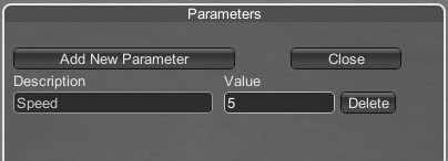
These I/O and parameters will be used in the body of the logic script code to manage the behavior of the UDC.
- Edit Parameters List: the UDC could have defined parameters list to add more levels of customization to the UDCs, use this button to create, edit, or delete the parameters List:
The index of the selected item in the list can be read in the script code using the following function:
UC.GetParameterList(string parameterName);
Example:
int selected = UC.GetParameterList("Type");
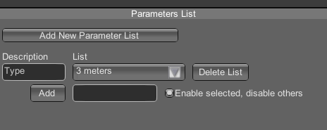
Press the Add button in order to add more items to the selected list. If the check option 'Enable selected, disable others' is enabled, the user action to select an item from the list will have a special behavior, in this case all children of the first level of the UDC will be disabled, and only the first level child of the UDC with the same index as the selected list item will be active. This is useful to create different types or versions of the same UDC in the same UDC container and the user will select the desired one.
Example:
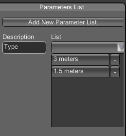
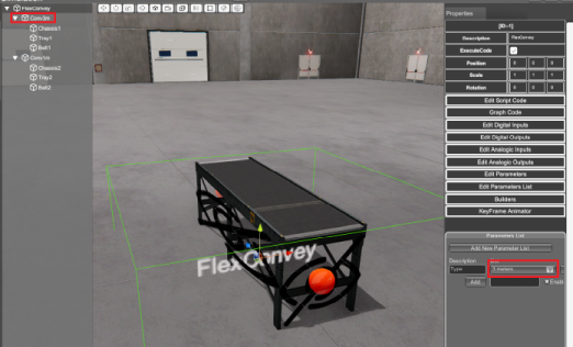
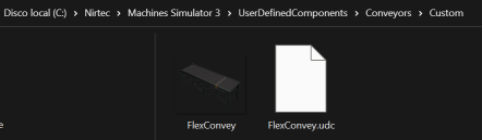
For this UDC it has one parameter list called Type and has two items in the list: 3 meters and 1.5 meters
When the user selects the first item of the list (3 meters) only is visible and active the first level children Conv3m from the UDC FlexConvey:
If the user selects the second item of the list (1.5 meters) only is visible and active the second level children Conv1m from the UDC FlexConvey:
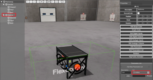
Remember that the first level child enabled and active of the UDC will be the one that matches the index of the selected list of items, if the 'Enable selected, disable others' check option is active.
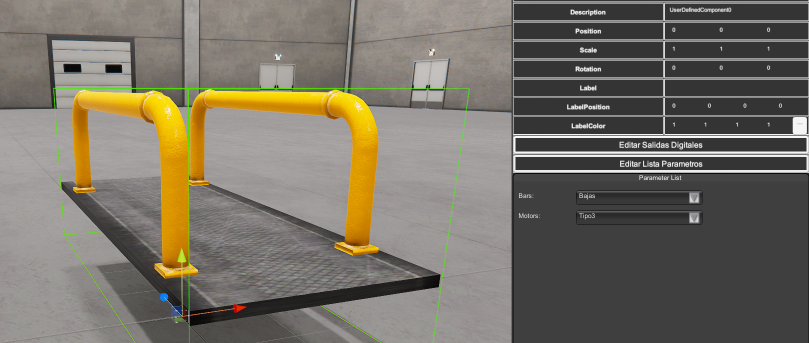
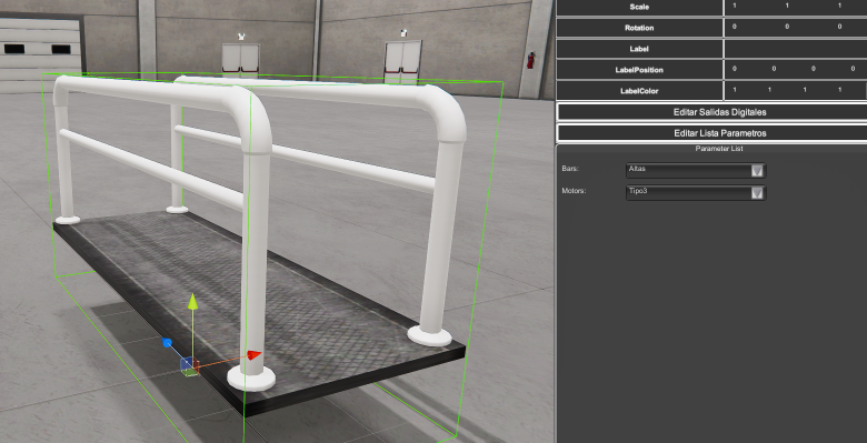
Using Parameter List to create components with multiple configurations
Parameters List can also be used to create UDC components with multiple mechanical configurations, for example, a conveyor with different motor configurations or supports, a platform with different textures, railings, …
To do it use the property Visibility and Invisibility of each parameter list element:
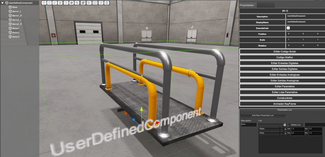
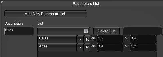
For each item in the parameter list, you can config in the Visible Text Container (‘Vis’) the id number of the components to be show and to hide in the Invisible Text Container (‘Inv’). Then when this item is selected in the list, the selected items will be shown or hidden:
- Builders: Allows to assign up to 6 build points on each side of the component (X, -X, Y, -Y, Z, -Z) to place new UDCs automatically. This tool will allow to the user who is using the UDC to place news UDC connected perfectly with this one (see next Builder section for more info).
- KeyFrame Animator: same as Empty component each UDC has a KeyFrame Animator tool to configure animations (see How to use the KeyFrame Animator Tool).
Please refer to the Programming Reference section to get the information about programming.
How to add Components to UDC
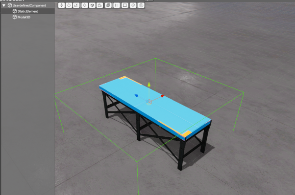
To add new components to the UDC, please take care the UDC hierarchy tree is selected, and make double click in the component you want to add in the Components tree, then this component will be added to the UDC:
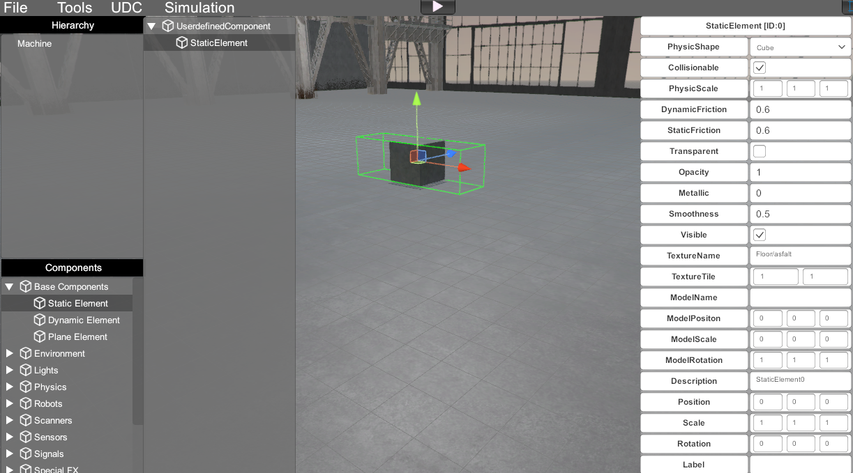
Clicking in the component, you can customize it using their property grid.
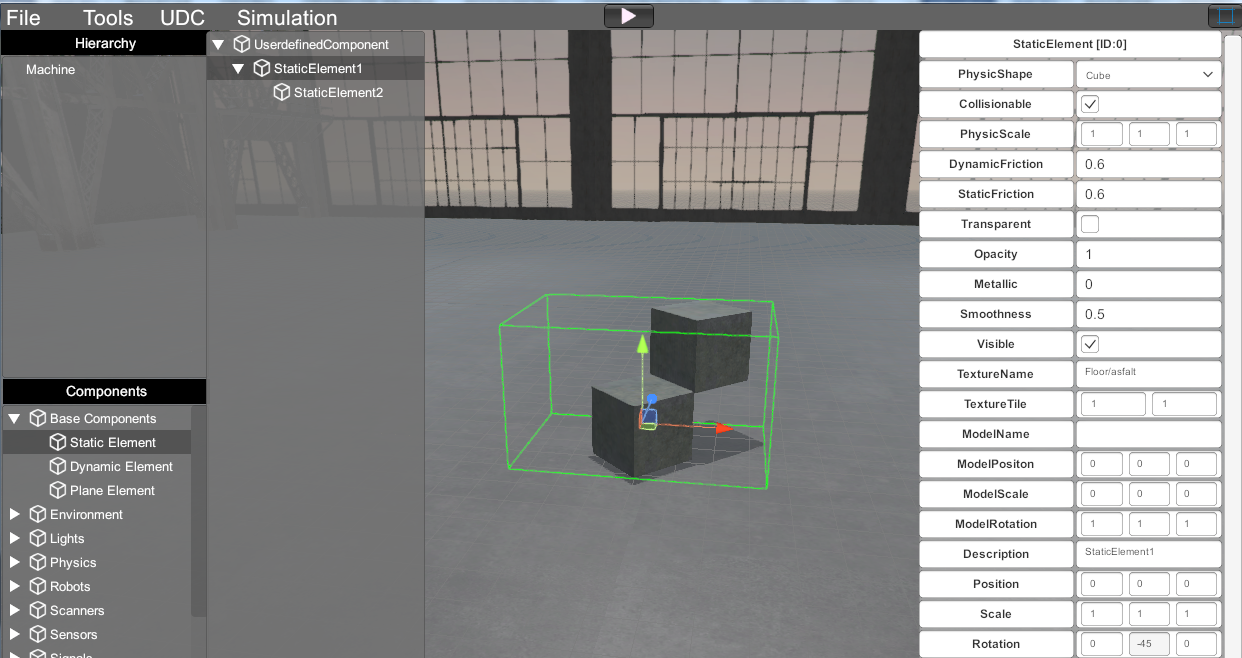
Parenting components
An important feature is the component parenting, this is, to make components children of other. For example, in the next image, we have parenting the StaticElement2 with StaticElement1. This is very useful because all the 3D operation with parents (like position, rotation and scale) will affect also to the children:
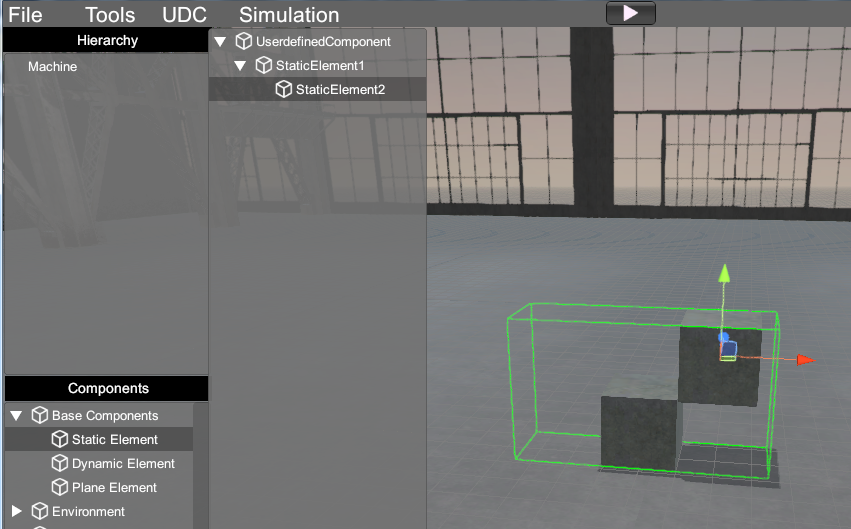
Then if we rotate StaticElement1, also rotates StaticElement2, but for StaticElement2 the origin is StaticElement1 like will be connected.
This simplifies a lot the logic, because we only must apply script commands to the parent components.
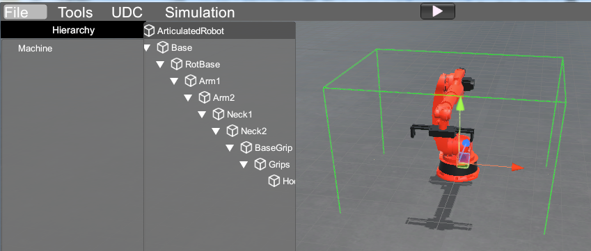
Other example is, for instance, the Articulated Robot UDC, here we have all the robot components connected, then we apply movement only to the required axis, the other components will be affected by the component of their parent and moves all together like will be physically connected:
Once a User defined Component is created is saved in the folder:
C:\Nirtec\Machines Simulator 4\UserDefinedComponents\Your Category Folder\
(Where C:\ is the installation drive you have chosen during the software installation).
You can open, copy & paste your different User Defined Components (.udc) created by you or other users placing the files in the indicated folder.
Builders
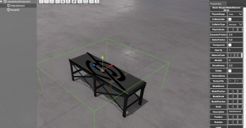
For the builder system to work correctly, the UDC created must have certain characteristics, the first component must be a Static Component and it must have the appropriate shape to fit with the other UDC components that can be called through the builder controls.
As the function of the Static component will only serve as a guide for the builder system, in this case the Visible property is set to OFF:
Now click on the UserDefinedComponent and click in Builders button, in the right button window will configure the following properties:
- Builder in +Z/-Z/+X/-X/+Y/-Y: activating/deactivating the check you will enable/disable the builder tool in the locations: front/back/right/left/up/down.
- Tags: here you must to set the tags name for the components that will be shown once the user press on the builder control. You can type as many tags you need, use the ‘
;’ character to separate it. - UDC Connection Tag: here you must type the tag assigned to this component for each side where could be connected with other UDC using their builder tool.
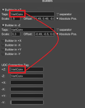
- Scale: sets the builder scale to customize the point size.
- Offset: by default, the builders are located in the front/back/left/right/up/down position of the Static Element that must be the first child of the UDC. This is used to set the size of the bounding box used to place the connected UDC with this one. But if you need to place the connected UDC in a different position, use this Offset property to set the X, Y and Z offset positions for each builder. The property consists of a Vector3 data type, that is, three floating point numeric values separated by the comma character ‘
,’ - Absolute Pos: by default, is disabled, this means the new UDC will be placed taking into account the dimensions of the UDC to be connected and the connected. But if you want to place the connected UDC just in the builder position, activate this property.
Example:
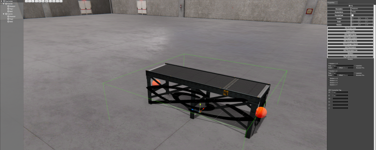
UDC Organization
Starting version 3.17 the UDC are organized according the following structure:
All the UDCs must be located in the folder C:\Nirtec\Machines Simulator 4\UserDefinedComponents\Your Category Folder\
(Where C:\ is the installation drive you have chosen during the software installation).
You can create as many folders inside the \UserDefinedComponents\ folder as needed, this will be use as the category to classify the UDCs:
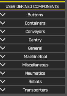
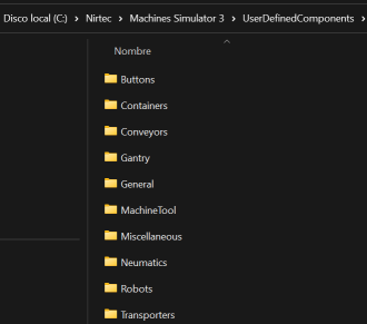
The Folders can contain any level of subfolders to create subcategories and organize the UDCs according these subcategories:
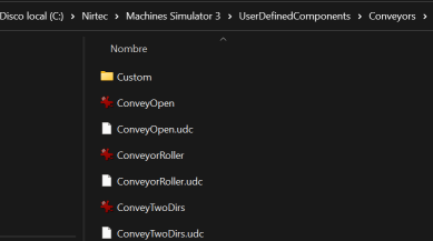
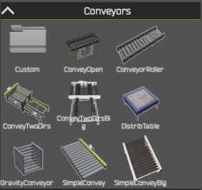
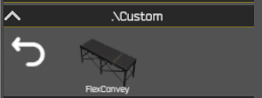
- Click on the Folder name to enter in the folder path and see the available UDCs located there.
- Click the Back arrow button to go up a folder level.